


 842 / 1575

ELECTRICAL
22
sunk screws such that the projection of the cover
plate is towards the rotor.
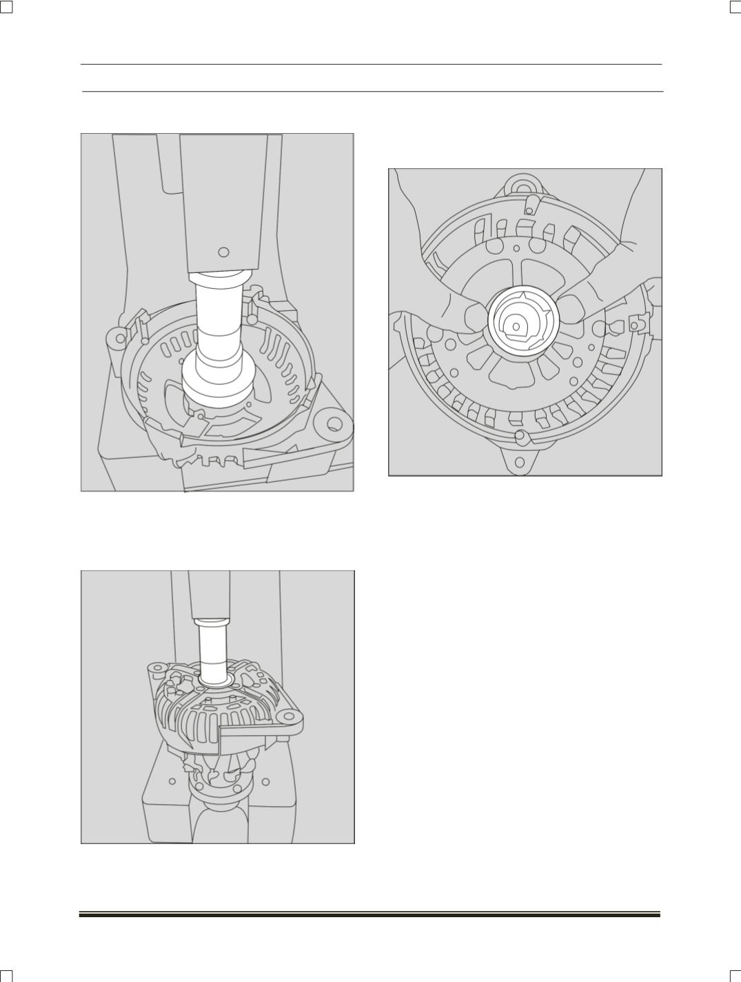
3.2 Rotor assembly in to the DEF:
Place the rotor as shown; put the drive end shield
on the rotor shaft as shown, press in the drive end
flange by a Spacer ring using an Arbor.
3.3 Slip ring assembly:
Press the fitting ring into the slip ring end shield,
ensuring the opening of the fitting ring towards the
mounting position of the voltage regulator.