


 841 / 1575

ELECTRICAL
21
ELECTRICAL
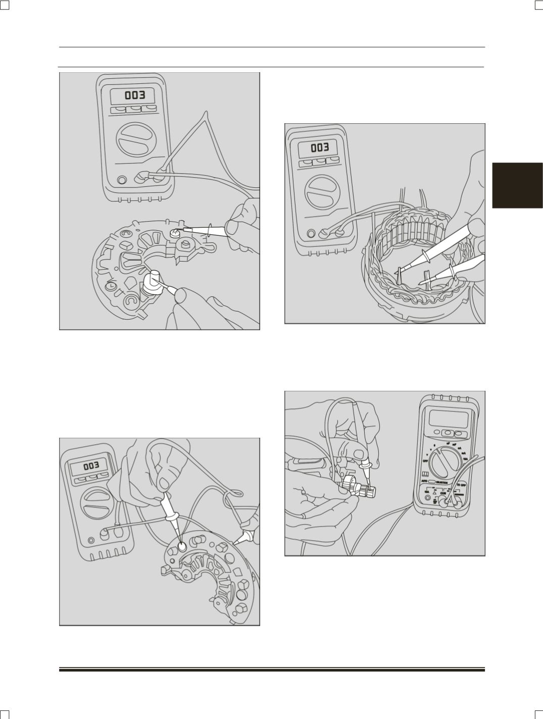
2.1.2 Testing of Negative power diode:
With red probe of the multi-meter on the lower hear
sink into which the negative power diodes are
pressed i.e. D- and black probe on the M1 ,M2
,M3 the multi-meter reading should be with in
0.300V and 0.900V. Interchanging the probe
(black
on D).
No current should flow. Even if one diode
found defective in the above tests, the rectifier
assembly has to be replaced.
2.2 TESTING OF STATOR.
Using Multimeter, check the resistance between
the phases of the stator winding. The resistance
should be 0.040 ± 10% ohms per phase.
2.3 TESTING OF ROTOR:
Measure the resistance of the rotor winding at the
slip ring with multimeter. Resistance should be 2.1
± 10% Ohms at 20 deg c or 3 ± 10% ohms at room
temperature.
3.0 ASSEMBLY
3.1 Bearing Pressing in DEF:
If the bearing in the drive end shield (
DEF
) has
been discarded. Press in a new bearing using an
Arbor press. Assemble the bearing holding cover
plate on the drive end flange using four counter