


 840 / 1575

ELECTRICAL
20
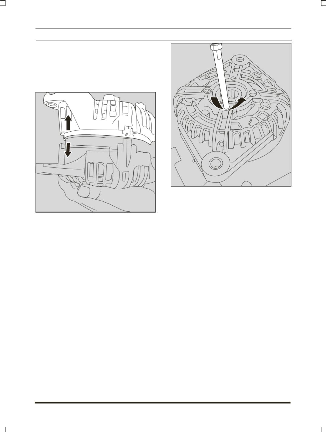
1.6 Dismantling of DEF, Stator, and SRES:
Mark the relative positions of the drive end flange
(DEF),
the stator and slip ring end shield
(SRES)
with respect to each other using a marker. Remove
the four screws .This will facilitates dismantling of
these three components. Pull off the fitting ring
from the SRES.
1.7 Dismantling of DEF
(Drive end flange
assembly)
:
Unscrew the four counter sunk screw, remove the
cover plate. Examine the ball bearing for excessive
play. If the play is noticeable press out the bearing
using an Arbor press and a suitable mandrel.
2
.
TESTING INSTRUCTIONS:
2.1. TESTING OF RECTIFIER.
2.1.1 Testing of Positive power diode:
Place the black probe of the multi-meter on the
terminal B+ and red probe on the each of the
points where the stator winding ends are soldered
on the rectifier
(Points M1, M2, M3, M4, M5,
M6).
Reading should be between 0.300V and
0.900V.Reverse polarity i.e red probe on B+ and
black probe successively on M1, M No current
should flow in this case i.e there should be ‘0’
change in the multi-meter reading.