


 806 / 1575

STEERING
40
NOTE
Use new metal strap for assembly.
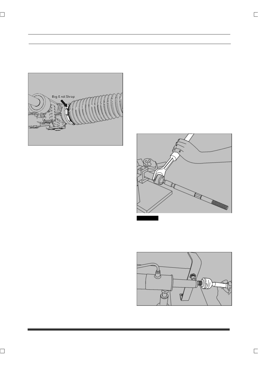
3. Put the bellow metal clip at the big end of bellow
and lock it using plier.
NOTE
Use new metal strap for assembly.
7.3.3.3 INNER BALL JOINT
(IBJ)
1. Remove the OBJ assembly.
(For procedure refer
OBJ dismantling procedure in this section.)
2. Remove the bellow from the IBJ.
(For procedure
refer bellow dismantling procedure in this sec-
tion.)
3. Keep the steering gear in centre position by ro-
tating the input shaft.
(Turn the input shaft lock to
lock and count the total number of turns and
bring back to the half of total turns for centre po-
sition from one end.)
4. Hold the rack using suitable tool which should
not damage the rack.
5. Unscrew the IBJ from the end of the rack using
open end spanner.
! CAUTION
Inner ball joints have left hand threads; it will tighten
when rotating in anticlockwise direction and loosen
when rotated clockwise when view from its OBJ
end.
6. Remove the IBJ from the rack assembly.
NOTE