


 1526 / 1575

HVAC
29
HVAC
INSPECTION OF MODE AND TEMPERATURE ACTUATOR
The actuator door flap is positioned on the mode/temperature detent select by the user by means of the re-
spective rotary knob. The control panel provides voltage corresponding to the user selected knob position.
The servomotor in the actuator cause the door flaps to move to the desired location and provide a feedback
signal to the control panel
.
1. To calibrate the actuator follow the below steps
2. Turn the IGN OFF and disconnect the battery.
3.Wait for approximately one minute and then reconnect the battery.
Once the battery is connected again wait for one minute and turn the IGN ON. Actuators are now calibrated.
Wait for one more minute after IGN is turned ON until the actuators are calibrated
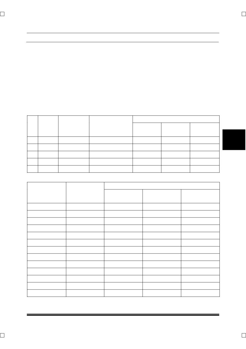
Feedback Signal Values for Mode Actuator
Sr.
No.
Detent
Position
Mode select-
ed
Knob angle in de-
grees (CW starting
from initial chest
mode)
voltage
Min (V)
Nominal (V)
Max (V)
1
1
Chest
0º
1.0
1.05
1.1
2
2
Chest-Leg
67.5º
1.6
1.65
1.7
3
3
Leg
135º
2.23
2.28
2.33
4
4
Leg-Defrost
202.5º
2.87
2.92
2.97
5
5
Defrost
270º
3.48
3.53
3.58
Feedback Signal Values for Temperature Actuator
Detent Position
Knob Angle in
Degrees (CW
starting from the
initial position)
Voltage
Min (V)
Nominal (V)
Max (V)
0
0
0.65
0.70
0.75
1
9
0.76
0.81
0.86
2
18
0.88
0.93
0.98
3
27
0.99
1.04
1.09
4
36
1.11
1.16
1.21
5
45
1.22
1.27
1.32
6
54
1.34
1.39
1.44
7
63
1.45
1.50
1.55
8
72
1.56
1.61
1.66
9
81
1.68
1.73
1.78
10
90
1.79
1.84
1.89
11
99
1.91
1.96
2.01
12
108
2.02
2.07
2.12