


 96 / 745

KRYOTEC ENGINE
88
59. Remove the hydraulic crane and sling form the
lifting brackets.
B. ENGINE FITMENT
1. Install the powertrain in the engine compartment
using a hydraulic crane and 1871001700 Sling
connected to the lifting brackets.
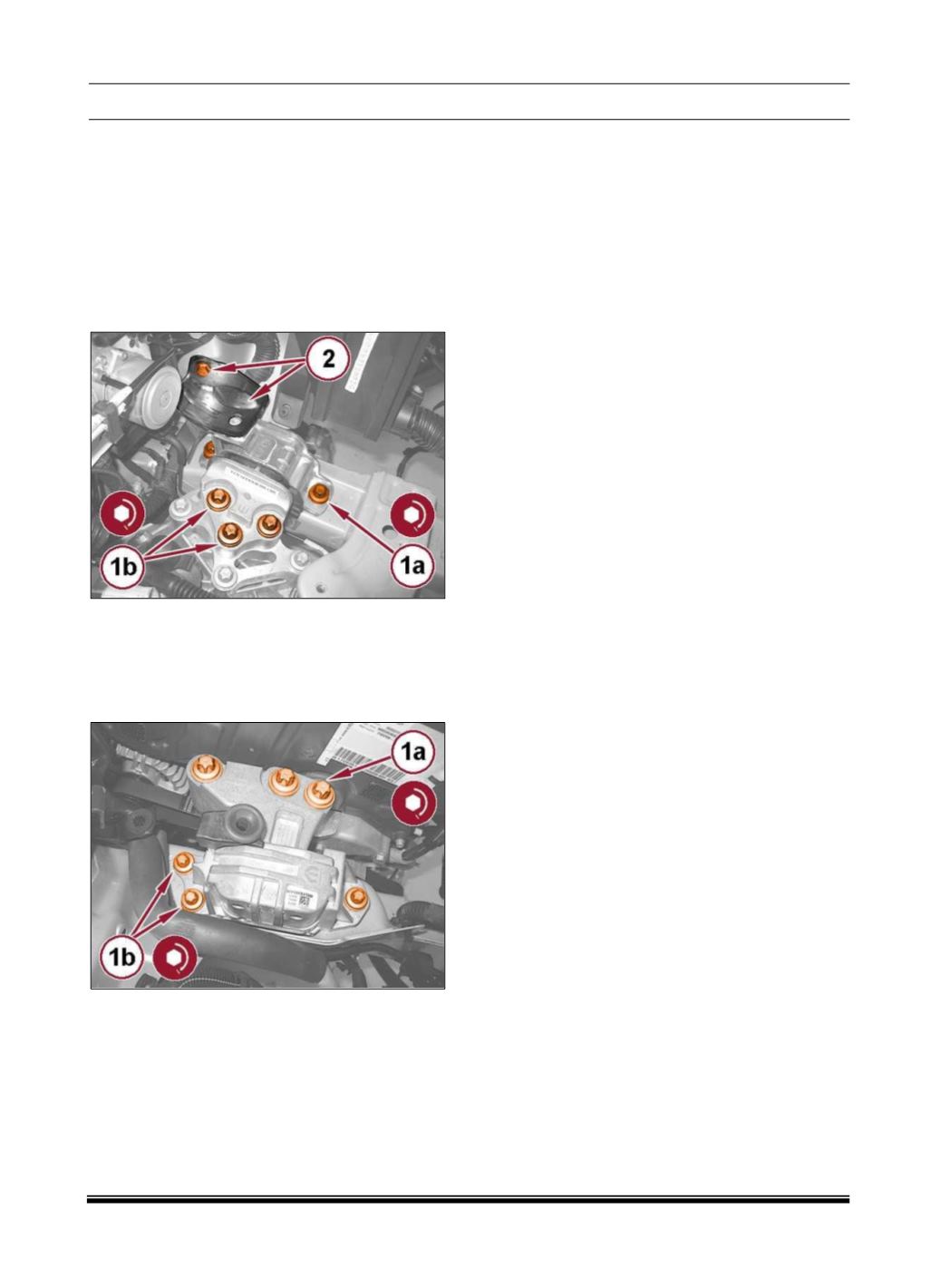
2. Install the left engine mount isolator and tighten
the bolts (1a) and (1b) to the proper (Torque
Specifications).
3. Install the support bracket (2) with the bolt
tightened to the proper (Torque Specifications).
4. Install the right engine mount isolator and tighten
the bolts (1a) and (1b) to the proper (Torque
Specifications).
5. Remove the hydraulic crane and sling connected
to the powertrain lifting brackets.
6. Install the fuel line retaining bracket with the
screw tightened to the proper (Torque
Specifications).
7. Connect the fuel supply line quick coupling.
8. Connect the fuel tank return line quick coupling.
9. Connect the engine wire harness connector and
engage the wiring to the spring retainer.
10. Connect the Powertrain Control Module (PCM)
wire harness connector and close the retaining clip.
11. Install the starter cable to the positive battery
terminal and tighten the nut to the proper (Torque
Specifications).
12. Pull back the lock sliders and engage the gear
selector cables to the brackets.
13. Open the retaining clips and engage the gear
selector cables to the lever arms.
14. Install the DPF differential pressure sensor with
the nut tightened to the proper (Torque
Specifications).
15. Connect the DPF differential pressure sensor
wire harness connector.
16. Connect the glow plug control unit wire harness
connector.
17. Install the pressurized coolant bottle and
connect the quick coupling.
18. Install the degas hose to the thermostat and
tighten the clamp to the proper (Torque
Specifications).
19. Install the air delivery pipe to the throttle body
with the screws tightened to the proper (Torque
Specifications).
20. Secure the air delivery pipe to the support
bracket with the screw tightened to the proper
(Torque Specifications).
21. Install the vacuum hose to the vacuum pump
and connect the quick coupling.
22. Connect the heater core hose quick couplings.
23. Connect the hose to the clutch slave cylinder
and engage the retaining clip.
24. Connect the coolant hose quick couplings.
25. Install the battery ground cable with the bolt
tightened to the proper (Torque Specifications).
26. Connect the reverse lamp switch wire harness
connector.
27. Install the left and right half shafts (Refer to 03
- Differential and Driveline/Half Shaft/Removal and
Installation).