


 959 / 1006

ELECTRICAL
132
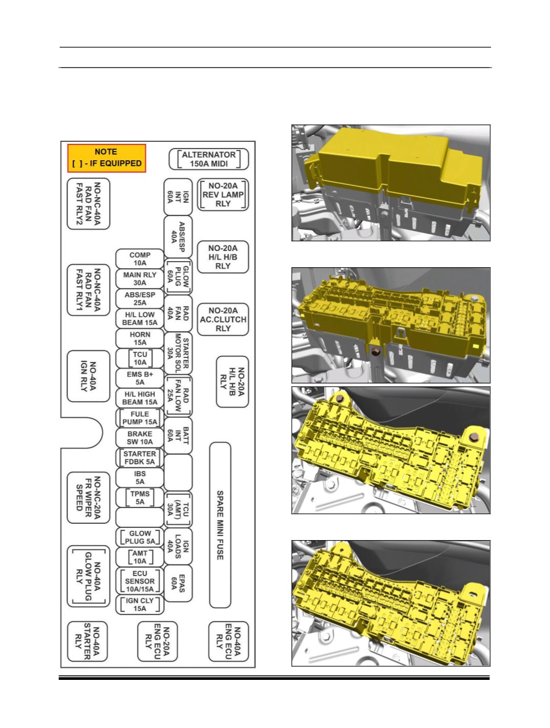
28.2 ENGINE FUSE AND RELAY BOX
NOTE
The fuse box layout is for reference purpose only.
Please refer the sticker provided inside the fuse
box cover.
REMOVAL
1.Remove the Battery. (Refer battery removal
process).
2.Remove the top cover of fuse box.
3.Remove the three mounting bolt of the fuse
frame assembly.
4.Gently pull out the fuse frame and disconnect all
the electrical connections.