


 958 / 1006

ELECTRICAL
131
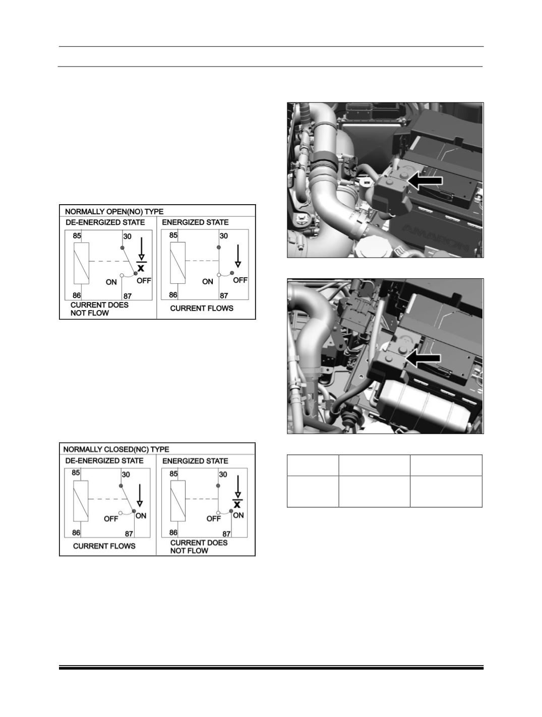
(a) The normally open-type
When a normally open relay as illustrated here is
checked, there should be no continuity between
terminals 30 and 87 when the relay is de-
energized. There should be continuity between
terminals 30 and 87 when battery voltage and
ground are applied to terminals 85 and 86. The
relay condition is determined by this check.
NOTE
Check the relay in both condition, i.e. energized
and not energized
(b) The normally closed-type
When a normally closed relay as illustrated here is
checked, there should be continuity between
terminals 30 and 87 when the relay is de-
energized. There should be no continuity between
terminals 30 and 87 when battery voltage and
ground are applied to terminals 85 and 86. The
relay condition is determined by this check.
NOTE:
Check the relay in both conditions, i.e.
Energized and not energized.
(c) The NO NC (Changeover) type
It has 2 relay out pins. One will be in contact in the
changeover state as in NC relay. When it is
energized it brakes the NC contact and connect
the other output pins.
28.1 BATTERY MOUNTED FUSE BOX (
BDU
)
BATTERY MOUNTED FUSE BOX (DIESEL)
BATTERY MOUNTED FUSE BOX (PETROL)
FUSE DETAIL
FUSE NO. FUNCTION
FUSE RATING
F01
STARTER
MOTOR
200 A
This fuse box is directly mounted on battery
positive terminal. Bus-bar type construction is
used.
WARNING
If Fuse box cover is removed for any reason, it
should be refitted properly at its original position.