


 607 / 1006

STEERING
3
D. GENERAL DESCRIPTION
The
EPAS
(
E
lectrical
P
ower
A
ssisted
S
teering -
column mounted) is made up of the following
components
The system consists of the steering column and a
servo unit. The steering torque is transmitted via
the intermediate shaft with universal joints to the
mechanical rack and pinion steering. Sensor
technology and torsion bar are next to the helical
gear drive in the servo unit. The helical gear drive
converts the support torque generated by the servo
motor and transmits it to the intermediate shaft.
The support torque and operating torque of the
steering wheel generated are transmitted via the
intermediate shaft to the mechanical rack-and-
pinion steering gear and then to the front wheels.
If the vehicle power supply or electrical supply fails,
then the vehicle can still be steered due to the
mechanical connection between the steering
wheel and front tires being steered.
EPAS system is equipped with following assist
feature
1. Speed Sensitive Assist Control
2. Active Return Control
FUNCTION
The torque sensor in servo unit registers the
steering torque and steering speed once the driver
performs a steering motion.
All data (including the vehicle signals such as
engine speed, vehicle speed, ignition signal) is
transmitted to the control unit (ECU). This then
calculates the necessary support torque and on the
basis of the calculated results, controls the servo
motor.
A rotor position sensor is attached to the servo
motor. An index sensor is integrated in the torque
sensor.
The control unit uses the integrated index sensor
and the rotor position sensor to calculate the
steering wheel’s steering angle.
Depending on the programming, the steering
wheel’s angle signal can be sent back to the
vehicle.
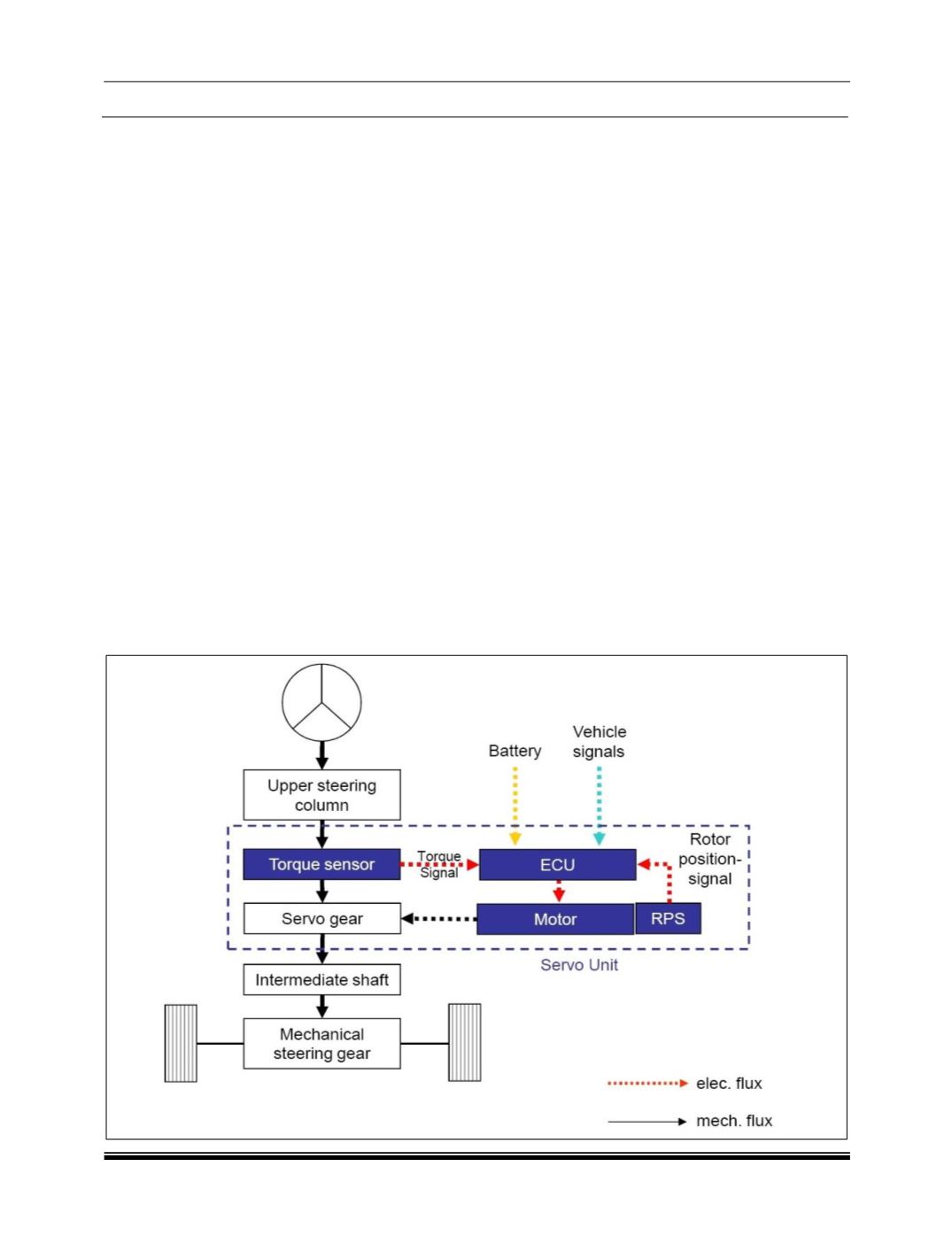
BLOCK DIAGRAM OF EPAS SYSTEM
: