


 428 / 516

FATC
41
2. Self made flushing fitments will be required as
AC system component fittings all differ in size,
shape and thread size.
3. When replacing air conditioning parts with new
ones, it is necessary to replenish oil by approxi-
mately the same amount which was left in each
part.
4. Reverse flush the components.
5. Do not flush through a compressor otherwise
possible internal damage could occur.
6. Recycle the refrigerant recovered during flush-
ing; the recovery device will remove
contaminants through a filtration system.
CAUTION
Be sure to use specified compressor oil only.
v. REPLENISHING COMPRESSOR OIL
a. While re-installing the Original Compressor
Drain and measure the refrigerant oil contained in
the compressor.
Charge oil through the discharge port of the com-
pressor with the same amount of new refrigerant oil.
NOTE
If the amount of oil in the original compressor was
not checked, then approximately 70±10 ml. of new
oil should be added to the compressor being in-
stalled. (This is assuming the compressor being
installed has first been drained).
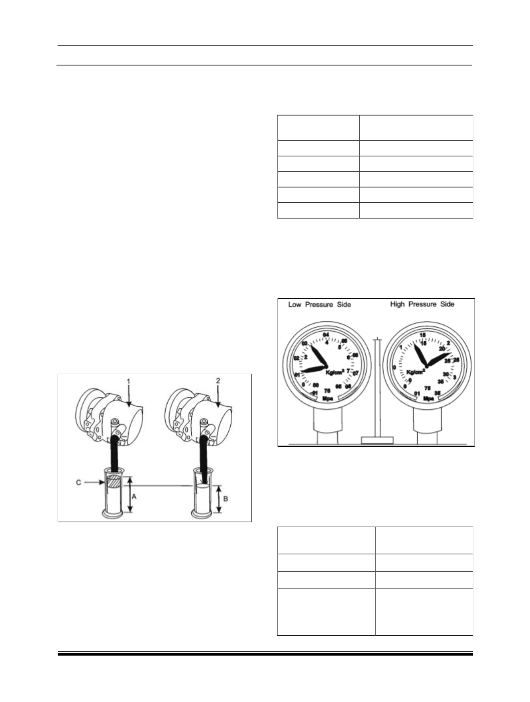
b. While installing a New Compressor
A new compressor (1) comes with a certain amount
of oil (A) sealed in it. When replacing the old com-
pressor (2) with a new one; an amount of oil (C) as
calculated below should be drained from the new
compressor.
“C” = “A” -“B” “C” = Amount of oil to be drained
“A” = Amount of oil sealed in a new compressor
“B” = Amount of oil remaining in old compressor (2)
NOTE
As it is necessary to replenish oil by approximately
the same amount, which is remaining in old com-
pressor, draining of additional oil from the New
Compressor becomes necessary.
Following table illustrates the amount of oil to be
replenish for respective HVAC/AC components
Replaced parts
Amount of compressor oil
to be replenished (in CC)
Evaporator
25
Condenser
40
Hoses
10
Pipes
10
Chiller unit
20
NOTE
When only charging refrigerant without replacing any
component, replenish the same amount of measured
oil when recovering refrigerant, if not measured, re-
plenish 30cc oil.
vi. PRESSURE TEST USING MANIFOLD GAUG-
ES
This is a method where trouble is detected and re-
paired by using manifold gauge. The manifold gauge
indicates the refrigeration cycle high and low pres-
sure side pressures on the respective gauge
NOTE
Make sure following conditions are fulfilled before
getting the correct gauge readings
A/C inlet temperature
(Ambient Temperature)
30° - 35° C (86° - 95° F)
Blower speed
High
Temperature Control
Full cold
Reference value before
AC operation at both
high and low pressure
sides
5-8 kg/ cm2 (0.5 - 0.8
MPa)