


 358 / 745

CLUTCH RELEASE SYSTEM
9
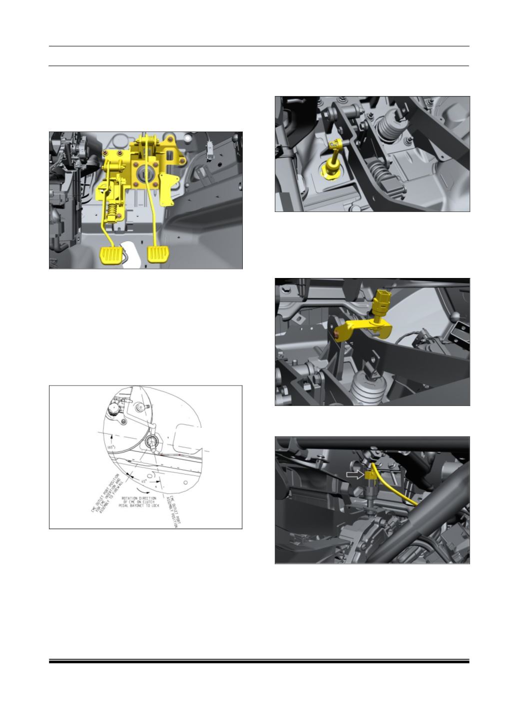
8. ASSEMBLY OF CLUTCH CONTROL
BRACKET
1. Position clutch control bracket Assembly on
firewall and tighten all Hex Flange nut M8
mounting with tightening torque 2~2.4 kgf-m.
2. Assemble Accelerator pedal Assembly.
(Follow
Accelerator
pedal
Assembly
procedure).
3. Insert the clutch master cylinder from engine
compartment to clutch pedal box through
firewall cut-out, ensure CMC aligned with
pedal box and rotate 45º anticlockwise till it
get lock and ensure suction port become
vertical.
(Ensure this is snap type
arrangement)
4. Insert the CMC eye (snap type) on clevis pin,
mounted on the clutch pedal box.
5. Ensure clutch pedal effort within (8.8) to
12.6kg, with release bearing load 1780 ±
180n (disc).
6. Fix stop light switch with bracket and tighten
mountings screw M6.
7. Connect Electrical connection to the stop light
switch.