


 259 / 418

BRAKES
30
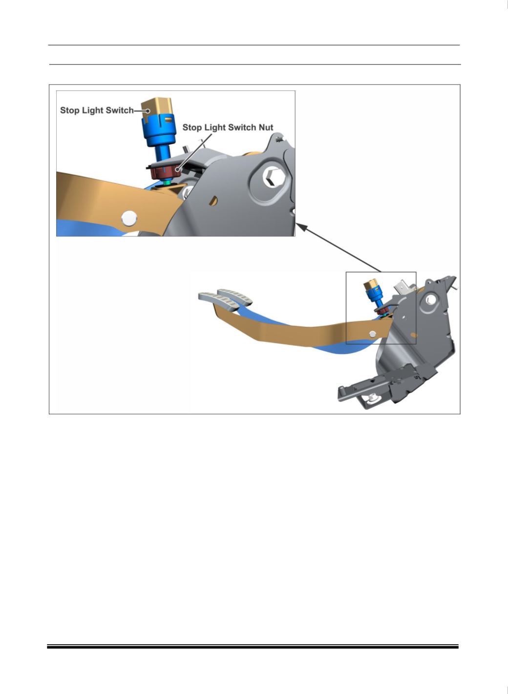
10.5. STOP LIGHT SWITCH ADJUSTMENT
NOTE:
Before performing stop light switch adjustment, ensure that booster is connected with clevis pin.
Ensure brake pedal is assembled with booster and confirm bleeding completed. This will ensure
brake pedal initial position,
(This is the condition to ensure prior to assemble of brake light switch.)
Do not press Brake Pedal while assemble Brake Light Switch.