


 451 / 924

SUSPENSION
32
9.6 ON VEHICLE REMOVAL AND ASSEMBLY
OF ANTI ROLL BAR
REMOVAL
1. Position the vehicle on two post lift.
2. Remove lower nyloc nut of ball joint securing
Stab link to the anti roll bar.
3. Do markings at the area shown by arrows,
before removing anti roll bar mounting clamp
bolts so that anti roll bar can be easily
centralized while installation.
4. Remove anti roll bar mounting clamp screw and
take out anti roll bar along with washer.
INSTALLATION
1. Mount anti roll bar but do not tighten the bolts.
Align paint mark with bush face to centralize anti
roll bar.
2. Ensure ball joint face of anti roll bar link is
parallel to mounting face of anti roll bar.
3. By holding the hex on the shank of the ball joint
with a spanner, keep on tightening the lower
nyloc nut till the threads protrude about 6 to 7
mm out-side the nut.
4. Tighten anti roll bar mounting clamp bolts.
NOTE:-
Bolt to be tighten in Pre-loading condition.
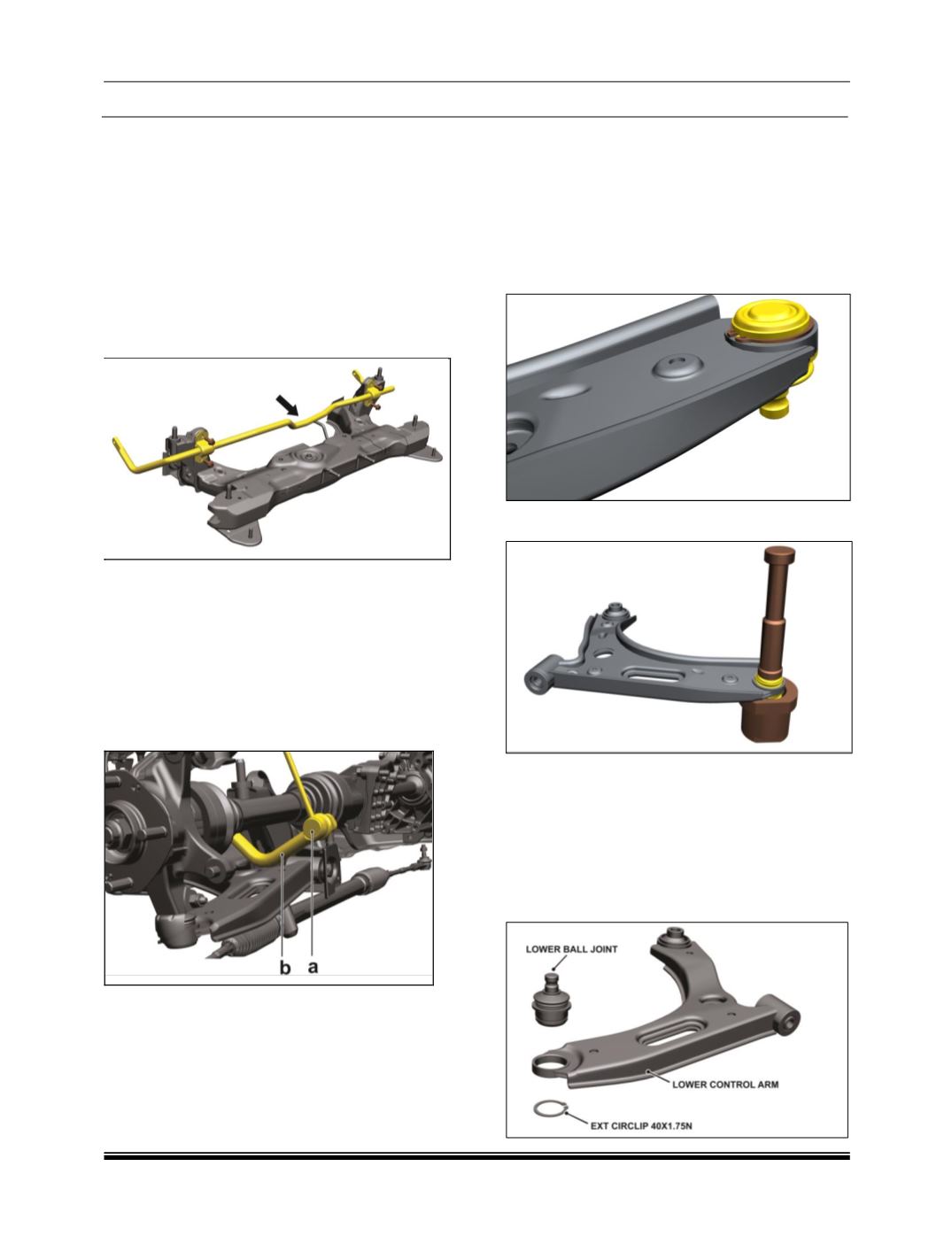
9.7REMOVAL AND ASSEMBLY OF LOWER
ARM BALL JOINT
REMOVAL
a) Support (part no. 5424 5890 3202) to be used
for ball joint removal.
b) Circlip to be removed before dismantle the ball
joint assembly from control arm.
c) Ball joint to be removed on hydraulic press.
d) Push out load to be applied on sealing
periphery (peened area) using special tool
(part no 2834 5890 2614) without contacting
the back plate.
ASSEMBLY
a) Support (part no. 5424 5890 32 02) to be used
for ball joint assembly on lower control arm.