


 112 / 948

KRYOTEC ENGINE
103
B. ENGINE ASSEMBLY
i. FITMENT OF CYLINDER HEAD SUB-
ASSEMBLIES
Refer “Repair and Inspection Details” section
before reusing components.
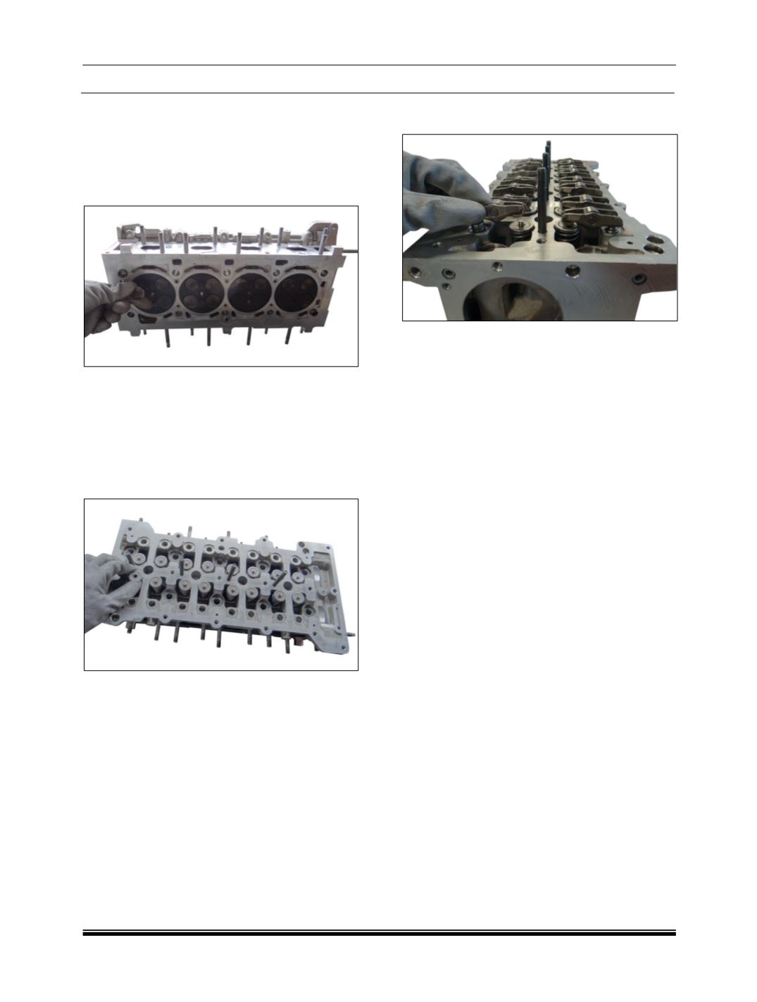
1. Fit inlet and exhaust valve from bottom side.
NOTE
Lubricate the valve stem and guide.
2. Fit the valve seats, valve retainers and using
special tool compress the valve springs and
place the spring lock halves.
(Handle -: 5530 5890 0101, Adapter -: 5412 5890
0606 & Support rail-: 5412 5890 0607)
NOTE
The lock halves hold the spring retainer in place
when relieving pressure applied by the spring
compressor.
3. Repeat the same procedure for all valves.
4. Install the roller finger follower and hydraulic
lash adjuster assemblies.
NOTE
Refer “Repair and Inspection Details” section for
repair details.