


 356 / 948

BRAKES
26
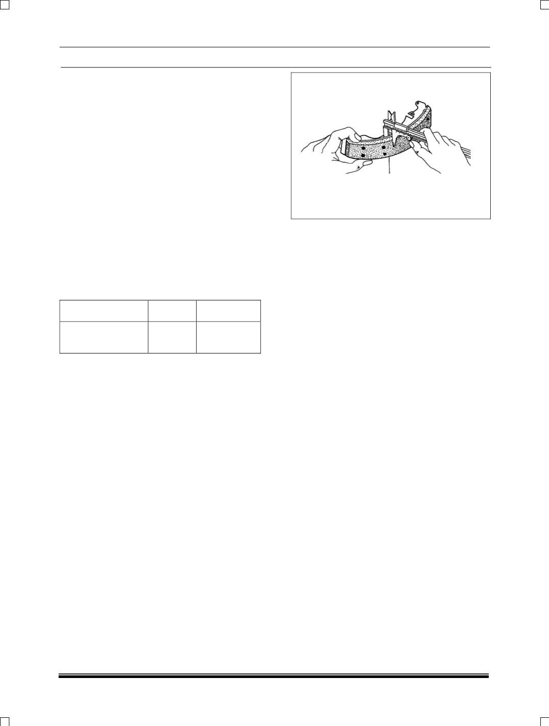
FITTING SHOES
ASSEMBLING
Lightly smear the following parts with special
grease as given. Keep the grease away from the
shoe linings and all hydraulic parts.
1. Tips of new shoes - High melting point grease.
2. Hand brake strut slots - Graphite grease.
3. Adjuster Pushrod Threads - Mineral oil base
grease.
Note:
When new shoe is fitted, ensure to fit new
shoe return springs also. Always fit new shoes in
pairs to both the sides of the vehicle. (RLH and
RRH sides)
Do not polish lining with sand paper or emery
paper. If lining is polished with sand paper or
emery paper, hard particles of sand paper will be
deposited in the lining resulting in damage of
drum surface.
Brake Lining
Standard Service Limit
Lining Thickness
above the rim
5.5 mm
1.0 mm
Refer to the illustration. Assemble the Auto
Adjuster (5.1, 5.2 & 5.3) to its minimum length.
Assemble the abutment end spring (8) between
the shoes. Place the shoes, springs along with
adjuster in position on to the platforms of the back
plate and locate the spring (8) below the riveted
abutment plate and the shoes in the abutment
groove. Hook the shoe return spring (7) (short
length coil) to the leading shoe, with the adjuster
assembly in its minimum length condition,
assemble the adjuster assembly between the
shoe webs. Attach the other end of the shoe
return spring (7) to the opposite end of the Trailing
shoe (3).Adjust the length of the adjuster until the
shoes will clear the wheel cylinder pistons.
Fit the pawl lever (18) to the spring dowel (20, 21,
22) inserting one leg of the pawl between male
push rod end and shoe web of the leading shoe
and the other end of the pawl leg resting on the
adjuster nut (11).Hook the short end of the spring
(19) into the hole in the pawl lever (18) and use
pliers to attach the opposite end of the spring on
to the shoe web (2).
Fit the shoe hold down springs (6), cup washer (5)
and pins (4) to both the shoes. Remove the elastic
band from around the wheel cylinder and reduce
the length of the adjuster assy. until the shoes rest
on the wheel cylinder pistons.
Fit the hand brake cable to the lever on the trailing
shoe, ensuring the cable is correctly located in the
end of the lever.
Note:
The cable should just be tight without
pulling the hand brake lever from the 'fully off'
position.
Ensure that the shoe linings (2/3) are free from oil
and grease.
During servicing of shoes/replacement, the brake
dia. overshoes should be set to 294 to 294.5 mm
by adjusting the ratchet.
This is to have minimum clearance between
shoes and drum.
Clean the exterior of the drum with a wire brush
and wipe the inside with a clean rag.
Note:
If the drum looks poor in condition, or is
scored inside where the brake shoes contact, fit a
new drum.
Offer the drum to the brake and adjust the length
of the adjuster until it is only just possible to fit the
drum over the brake shoes. Check the pawl is in
contact with the adjuster nut on the adjuster and
fit the drum. Repeat procedure with the opposite
rear brake and operate the foot brake through its
full stroke 10 to 20 times. Check the movement of
the hand brake and road test the vehicle.