


 299 / 1232

ENGINE 1.3 QUADRAJET (75PS)
74
ELECTRIC FUEL PUMP
The electric fuel pump has a permanent magnet
electric motor (1) which controls the pump (2) impeller
and a terminal support cover (3) which contains the
electrical and hydraulic connections.
The pump stage is the single, peripheral flow type
with high performance under low voltage and
temperature conditions.
FUELPUMPOPERATIONCHECKINGPROCEDURE:
a. Remove fuel filler cap.
b. Release the fuel system pressure. (Refer Fuel
pressure relief procedure)
c. Turn ignition switch ‘ON’
d. Check fuel pump operation by listening to the
sound at fuel pump end.
e. If no sound is heard, measure voltage between
fuel pump electrical connector wire to chassis
ground. The voltage should be approx. 12V.
f. If voltage is not correct, check for fuel pump relay
and related wiring harness.
g. If you do not measure 12V, check for continuity of
fuel pump connector as per circuit diagram.
h. If there is continuity, replace fuel pump.
i. If there is no continuity, repair the ground circuit.
FUELPUMPPRESSURECHECKINGPROCEDURE:
a. Release the fuel system pressure. (Refer Fuel
pressure relief procedure)
b. Remove fuel delivery connector.
c. Connect fuel pressure gauge (having a range of 0
- 10bar) to the delivery port of the fuel pump.
d. Confirm battery voltage (12V)
e. Turn ignition switch ON to operate fuel pump and
after 2 seconds turn it OFF. Repeat this 3-4 times
and measure fuel pump pressure. It should be 2.5
bar.
f. If it is not within specification, replace fuel pump.
1. If the pressure is high, check for
(i) Fuel delivery line for any blockage.
(ii) If the delivery line is clean, replace fuel pump.
2. If the pressure is too low, check for
(i) Block delivery line and check if pressure rises.
(ii) If pressure does rise, reassemble fuel pump.
(iii) If pressure does not rise, replace fuel pump or
check for leakages.
g. After checking fuel pressure, remove fuel pressure
gauge.
h. Connect fuel delivery connector to fuel pump nipple
and ensure that quick fix couplings are properly
fitted.
i. With engine OFF and ignition ON check for fuel
leakage.
C. FUEL LEVEL SENSOR
Fuel level sensor assembly consists of major parts
as TFR Holder assembly and Float Arm Assembly.
Fuel level sensor wiring harness is connected to
module connector (under the module cover). Fuel level
sensor assembly provides the signal to indicate the
fuel level in the tank. As the float arm assembly moves
w.r.tothe fuel level in t ank, resistance at sensor
harness varies accordingly.
REMOVAL:
1. Disconnect battery.
2. Remove fuel module assembly from vehicle.
(Refer Fuel module removal procedure).
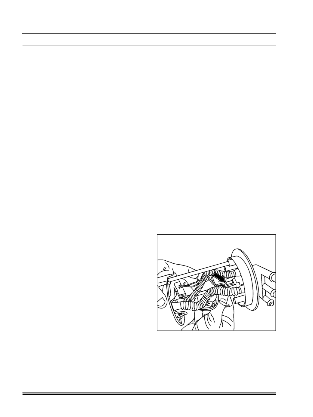
3. Disconnect electrical connector of fuel level
sensor.
4. Pry out two locks (using suitable tool) located at
either end of fuel level sensor.
NOTE:
Please note that level sensor holder has the
snaps on both sides. Enough care need to be taken
to avoid damages to the snaps onmodule and level
sensor