


 287 / 1232

ENGINE 1.3 QUADRAJET (75PS)
62
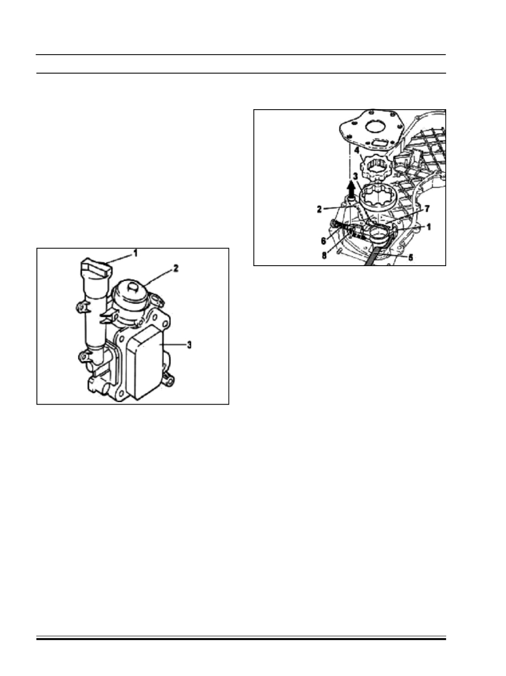
ENGINE OIL PUMP
1 – Partition
2 - Oil supply duct
3 - Driven gear
4. Drive gear
5 - Low pressure chamber
6 - Relief valve
7 - Pressure chamber
8. Duct between high and low pressure
B. CONSTRUCTIONANDWORKING:
The engine oil is drawn in by the sump by means of
the vacuum created by the rot ation of the gears on
the crankshaft.
There is a vacuum from the partition (1) for the gears
as far as the oil sump suction head.
The pressure develops starting from the partition (1)
in all the engine supply ducts (2).
When the pressure exceeds 5 bar, the force exerted
on the restrictor valve (6) overcomes the reaction of
the spring underneath and moves the valve until the
connecting duct (8) between the pressure chamber
(7) and the low pressure chamber (5) opens.
3A.1.2.5 LUBRICATING SYSTEM
The lubrication system of 1.3 QUADRAJET consists
of two main components which are Oil FilterAssembly
with Heat Exchanger and Oil Pump. It also includes
the various internal oil flow circuits and oil jets fitted
in the engine to lubricate the vit al areas and
components of the engine, including the line to
lubricate Turbocharger.
A. COMPONENTS
OIL FILTER AND HEAT EXCHANGER
ASSEMBLY
This assembly includes both the filter element and
the heat exchanger with the oil filler plug at the side.
1 - Oil filler plug
2 - Filter element cover
3 - Oil /water heat exchanger