


 278 / 1232

ENGINE 1.3 QUADRAJET (75PS)
53
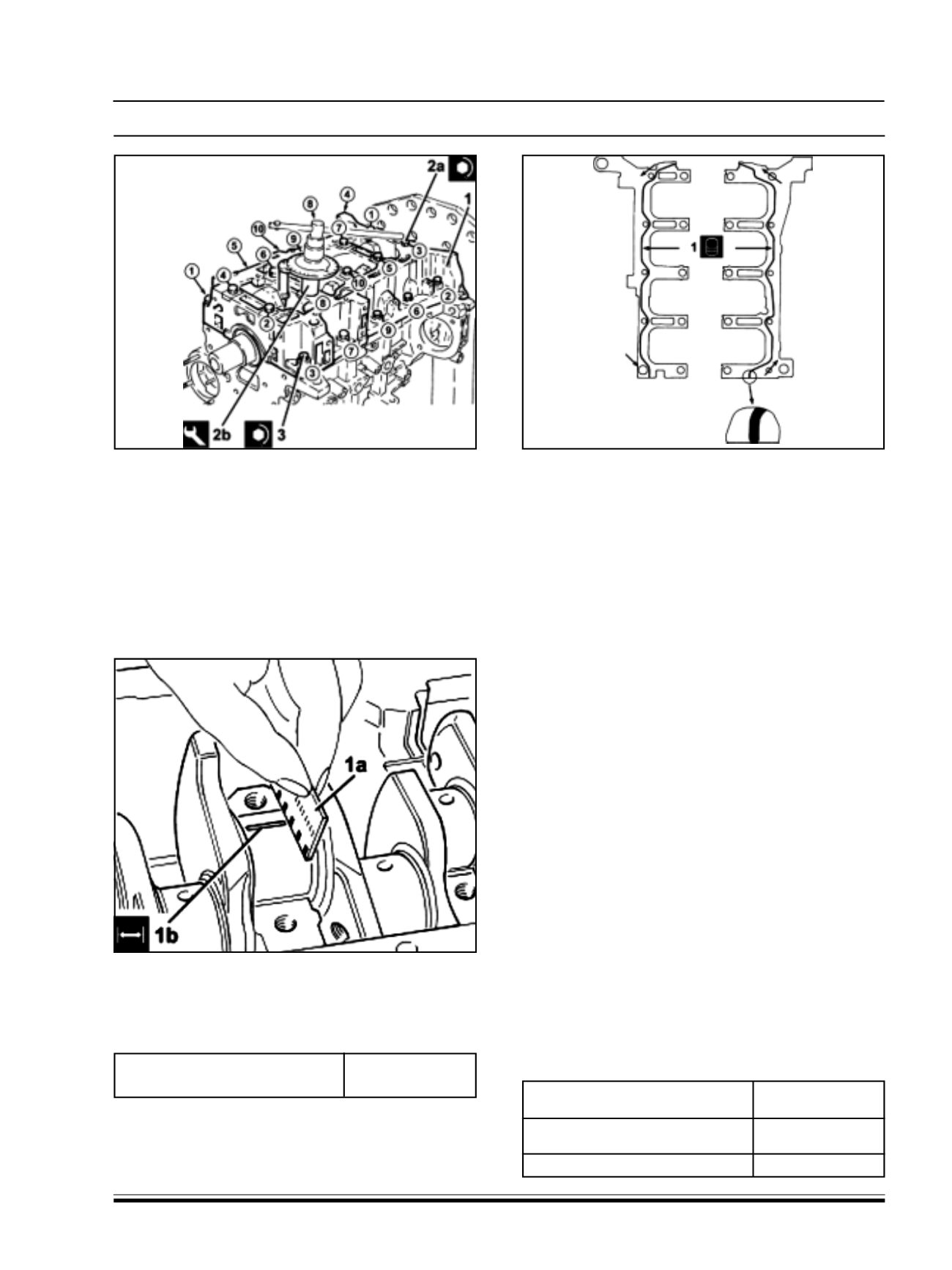
28.Refit the lower crankcase (1) with lower main
bearing halves in its seat.
29.Tighten the M10 central bolt s (2a) securing the
lower crankcase to the specified torque of 1.9 ~
2.1Kg-m + 80
0
+/- 3
0
, following the order shown in
the figure. Use the angular tightening tool (2b).
30 Tighten the lower M8 crankcase side bolt s to a
specified torque of 2.9 ~ 3.2Kg-m, following the
order shown in the figure.
31.Remove the lower crankcase with main bearing
halves fitted previously and, using a suit able
graduated measuring instrument (1a), measure
the clearance shown by the calibrated wire (1b).
Clearance between main bearings -
crankshaft main journals (mm)
0.028 ~ 0.048
NOTE:
If the figure measured is outside of the
tolerance, replace the half-bearings with ones of the
correct size nd category.
32.After checking all the main journals, apply a strip
of specified silicon sealant to the contact surfaces
between the lower crankcase and the upper
crankcase as shown in the figure above.
NOTE :
The sealant strip must be unbroken. The
sealant strip diameter must be 2.5 - 3.5 mm.
33.After applying the sealant clean the crankshaft
lower oil seal seat.
34.Fit the lower crankcase to the upper crankcase
permanently by tightening the bolt s as shown
previously.
35.Check that the small end bush bore (inner
diameter) diameter is within the recommended
limits of 23.006 mm ~ 23.012 mm; if not, replace
the connecting rod assemblies.
36.Check that the diameter of the gudgeon pin
housing in the piston is within the recommended
values of 22.990 mm ~ 22.996 mm.
37.Ifthe piston pin bore diameter is not within
specified values, replace the piston complete with
its piston pin and rings.
38.Check that the outer diameter of the piston pins is
within the recommended limit s of 22.982 mm ~
22.987 mm; if not, replace the worn piston pins.
39.Fit the piston rings in the cylinder bore and check
that the opening between the ends is within the
recommended values; if this is not the case,
replace the circlips.
Cylinder compression 1st sealing
ring gap (mm)
0.20 ~ 0.30
Cylinder compression 2nd sealing
ring gap (mm)
1.0 ~ 1.5
Piston oil scraper ring gap (mm)
0.25 ~ 0.50