


 570 / 1232

Automated Manual Transmission
42
tion indicated in the figure.
Place the gear selection actuator protective
cover back in its housing and tighten the
relevant screw.
Connect the electrical connection for the
oil pressure sensor and engage the wiring
with the retaining clip.
Connect the electrical connection for the
gearbox input speed sensor.
Connect the pipe from hydraulic unit to
clutch release actuator, hydraulic unit side,
complete with new O-rings, and engage the
retaining clip.
Tighten the connector for the pipe from
electric pump to solenoid valve unit, sole-
noid valve unit side.
Connect the return pipe from solenoid
valve unit to reservoir, solenoid valve unit
side and tighten the relevant band.
After having refitted the gearbox in the ve-
hicle, connect the diagnosis equipment and
carry out the following operations:
Hydraulic system for gearbox with hy-
draulic selection – Bleed air.
Clutch self-calibration enablement.
Grid self tuning - service.
New actuators (only if the hydraulic actu-
ation unit is being replaced).
Hydraulic Speed Selection Hydraulic Actua-
tor Unit and Clutch Removal:
Place the car on a lift.
Position the gear lever at N.
Connect the diagnosis equipment and carry
out the accumulator depressurisation pro-
cedure.
Remove the Protection / guard under the
engine.
Disconnect the battery and remove the
battery support / drip tray.
Remove the wiring for gearbox hydraulic
selection system on hydraulic selection
unit.
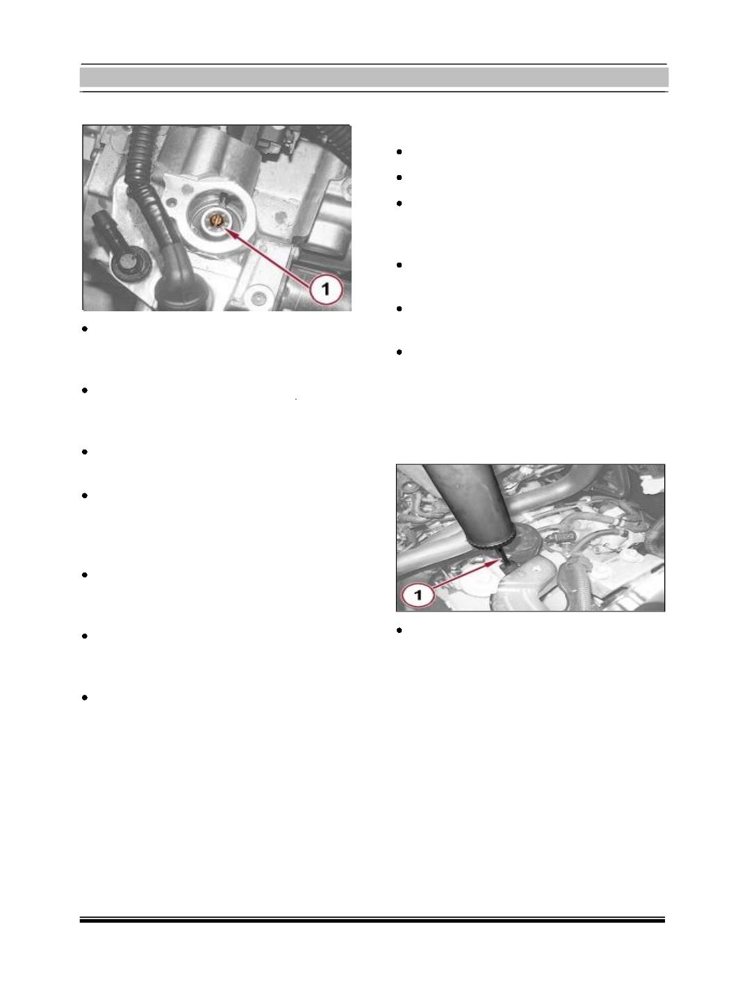
1. Unscrew the plug and draw off the fluid in
the electro- hydraulic selection gearbox
hydraulic circuit using a suitable syringe.
Screw in the electro-hydraulic selection
gearbox hydraulic circuit fluid reservoir
plug.
1. Loosen the band and disconnect the pipe
from hydraulic unit to reservoir, hydraulic
unit side.
2. Raise the retaining clip and disconnect the
pipe from hydraulic unit to clutch release
actuator complete with O-rings.