


 667 / 1265

Nexon AMT Routine Procedure for Component replacement
Version: 2.0
Date: 15-Oct-17
Author:
Suraj / Anupama Gore
Page: 5 of 18
Copyright ©
TATA MOTORS Ltd.
This document must not be used in any way, such as copying and redistributing to third parties, without the consent of author.
6
Routine Procedure for Component Replacement
6.1
Matrix of Routine Procedure for Component Replacement
This matrix is a brief reference on sequence and not a complete guide for any routines/replacements, step
by step procedure described in this manual to be followed for any routines or replacements.
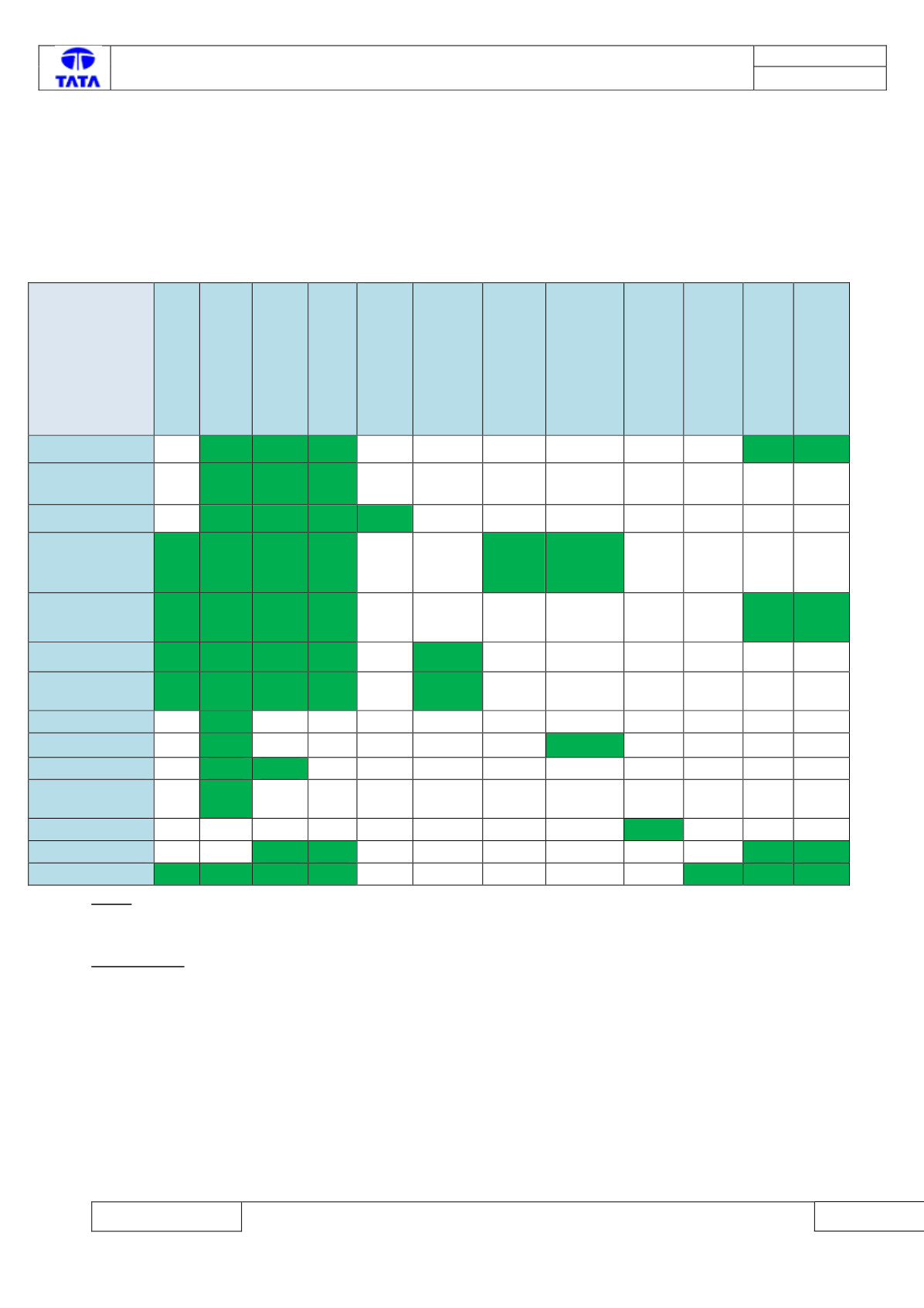
Component
Replacement
Clut
ch
Circ
uit
Blee
ding
Hydr
aulic
Circui
t
Depr
essur
izatio
n
Clutc
h Kiss
Point
Self
Tunin
g
Grid
Self
Tuni
ng
Reset
data
after
gear
box
replac
emen
t
Reset
data
after
Clutch
compon
ent
replace
ment
Reset
Data
After
Pump
Replac
ement
Reset
Data
After
Accumul
ator
Replace
ment
Reset
Data
After
shift
lever
Replac
ement
Reset
Data
after
AMT
Kit
Replac
ement
Read
Stati
stical
Data
Write
Statis
tical
Data
TCU
1
5
4
2
3
Actuation
system
1
3
2
Gear Box
1
4
3
2
Pump/Accumula
tor/Clutch
actuator
5
1
6
4
2
3
Valve block +TCU
Replacement
6
1,5
7
4
2
3
Clutch
3
1
5
4
2
Clutch Position
Sensor
3
1
5
4
2
Reservoir
1
Electric Motor
1
2
Rubber Bellow
1
2
Primary shaft
speed sensor
1
Gear Shift Lever
1
TCU Flashing
3
2
1
4
AMT Kit
5
1
7
6
4
2
3
Note-
1.
Nos. written in the green boxes of the matrix represent their priority in execution (no.1 written
against the particular routine needs to be performed first and so on).
For example-
If you have replaced the TCU in the vehicle, you need to execute the routines in following sequence.
1.
Hydraulic Circuit pressure depressurization
2.
Read Statistical Data
3.
Write Statistical Data
4.
Grid Self-tuning
5.
Clutch kiss point self-tuning