


 451 / 1034

DRIVETRAIN-TA65 Star
66
20. Place 5th gear assembly (lay shaft) with bush
and needle cage and synchro pack (5/R) along
with shifter fork (5th gear) on shifter sleeve.
Locate shaft hole on shifter fork to shifter shaft.
21. Lock the shifter fork on shifter shaft by spiral
pin.
22. Place lock plate on lay shaft 5th gear assembly
23. Fix lock nut on lay shaft.
24. Lock the input shaft from below. Engage any
one of the gears.
25. Tighten the lock nuts on both lay shaft and
input shaft by giving torque of 12.3-16.7 mkg.
26. Stake the collar of both lock nuts on lay haft
and input shaft.
27. Check the correct positioning of shifter shaft by
moving gear shifter shaft assembly in neutral.
Assemble the speedo sensor back on the rear
housing.
28. Place assembly rear cover with liquid gasket
on housing (rear half) and fix it by assembly
hex screws (3Nos.).
29. Tighten the screws to specified torque.
NOTE:
Clean the front half and rear half interfaces/ so
that no cured and dried liquid gasket remained are
left on the machined surfaces.
30. Unlock the input shaft from below.
31. Fix reverse light switch on housing (rear half),
Fix magnetic drain and filter plugs with new
washers.
32. Fix the C-mount bracket on the gear box front
housing.
33. Fix the B-mount bracket in the correct
orientation.
34. Unscrew 3 mounting bolts (M8) and dismount
the transaxle assembly from adaptor plate on
work sand.
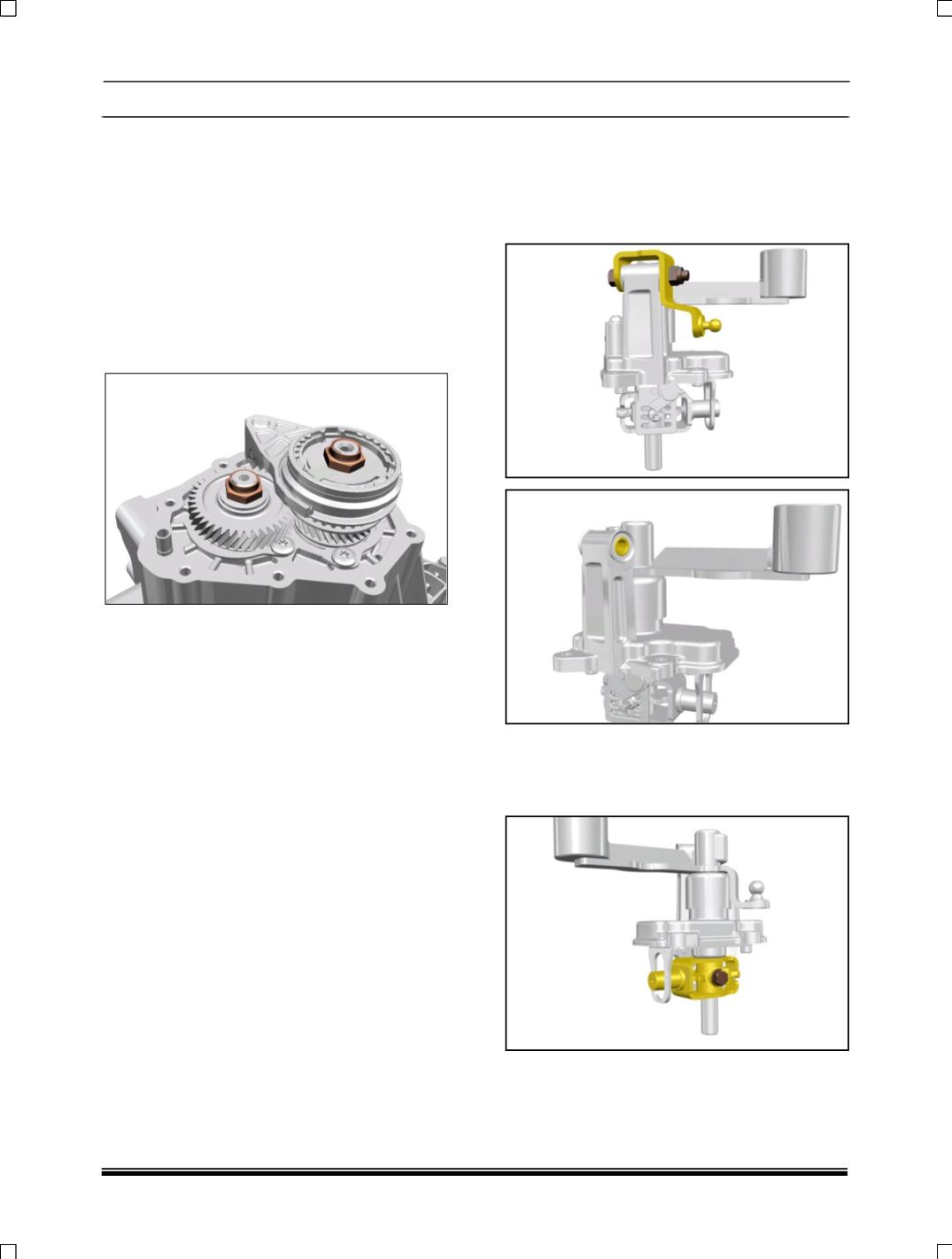
S. ASSEMBLY OF TOP COVER:
1. DISMANTLING:
1. Loosen the M8 Nut and remove the bell crank
lever assembly along with bellow and bush,
spacer & sealing ring as shown below figures.
2. Loosen the cross pin bolt of selector shifter
shaft to remove the interlock piece along with
barrel spring, Central Detent and finger
(selection and shifting).