


 449 / 1034

DRIVETRAIN-TA65 Star
64
5890 3507.
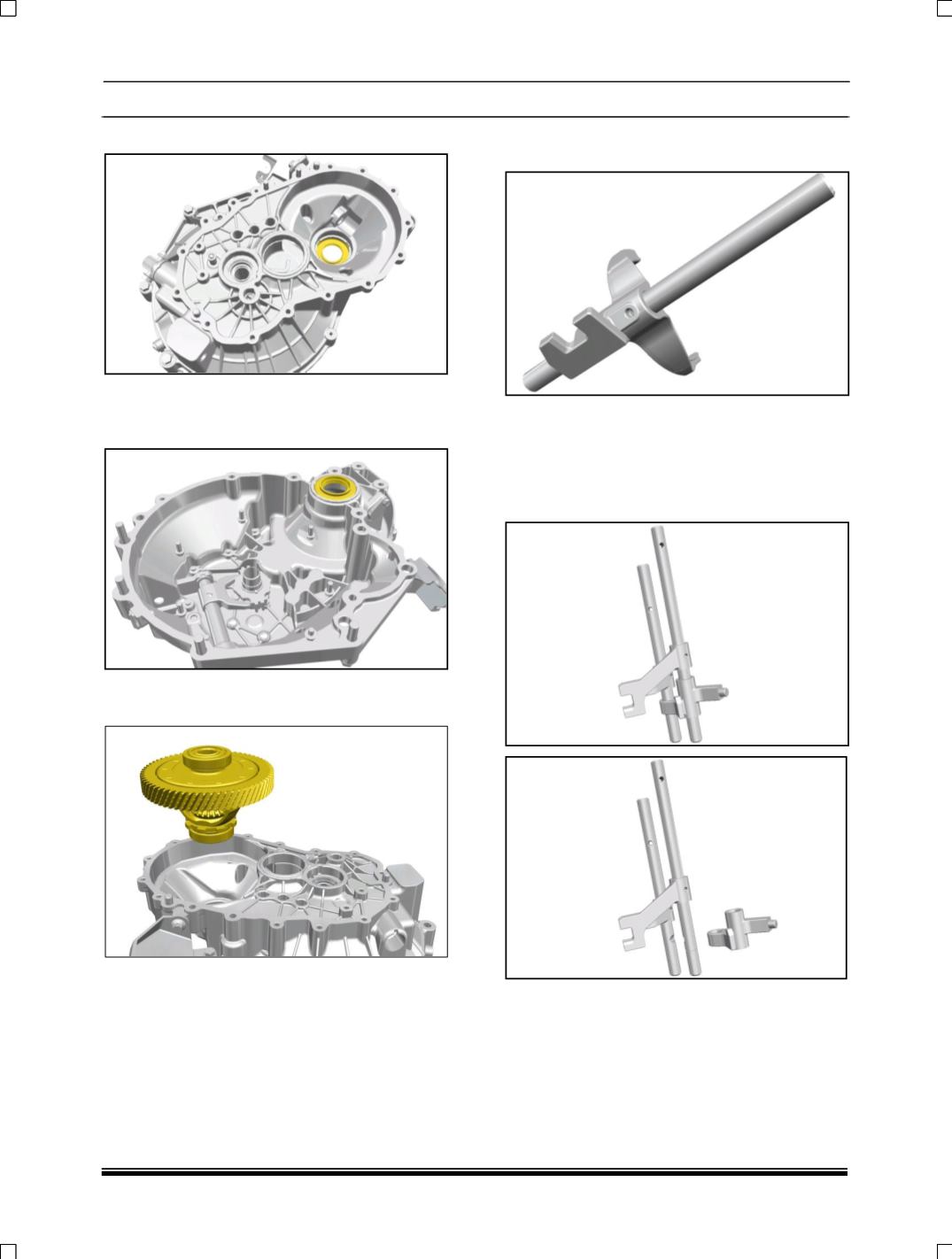
4. Remove sensing wheel using by puller part no.
2651 5890 3506 and rest pad part no. 2702
58902612N.
5. Place the assembly differential in front half
housing.
6. Fix the shifter shaft to the shifter fork of first
and Second gear and lock it by dowel pin.
7. Insert the third and fourth, fifth and reverse
shifter Shaft after locking by interlock balls and
with Shifter dogs fitted.
8. Insert the third and fourth, fifth and reverse
shifter Shaft after locking by interlock balls and
with Shifter dogs fitted.