


 920 / 1906

TOD
40
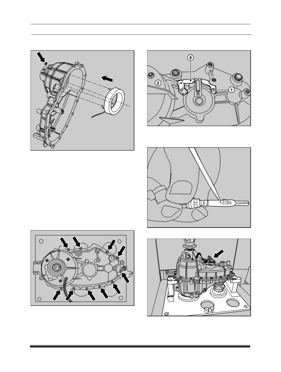
4. Install the clutch coil assembly inside the cover
and tighten three nuts.
NOTE
Before assembly, check the clutch coil for its
proper functioning by checking the resistance
value.
The coil resistance should be in the range of 2.375
to 2.625 Ohms at 25º C.
5. Apply 1.6 mm bead of LOCTITE RTV 598HB to
the transfer case-mounting surface. For
installation of cover, align the cover with
transfer case. Do not use excessive force.
6. Install the cover onto the case and tighten 15
bolts positioning identification tag.
7. Install the bracket
(3)
to the cover along with
the “J clip”
(2)
and tighten two bolts
(1)
.
8. Push the strip of the clutch coil connector
upwards and press the coil terminal into the
connector.
9. Lock the connector on to the bracket.