


 405 / 1906

ENGINE
171
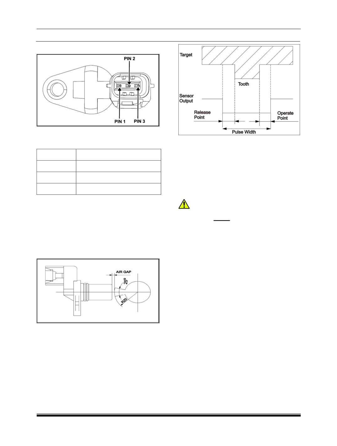
CONNETCOR DETAILS
PIN DETAILS
PIN NO
DESCRIPTION
Pin 1
Power supply
Pin 2
Signal
Pin 3
Earth
REMOVAL
1. Remove engine cover.
2. Disconnect the wiring harness connector from
cam shaft position sensor.
3. Remove one mounting bolt of sensor and take
out the cam position sensor from its location.
INSPECTION
1. Using multimeter measure the voltage across
the pins of cam sensor.
With ignition ‘ON” voltage between pin 2 & 3 is
as below,
4.7 V (
When the flag is not in front of the sensor
)
0.6V (
When the Flag is in front of the sensor
)
REFITMENT
1. Locate the cam shaft position sensor and fit one
mounting bolt and tighten with specified torque.
Tightening torque for bolt – 1 Kgfm
2. Connect the wiring harness connector to the
cam shaft position sensor.
3. Fit engine cover.
CAUTION:
Cam Sensor
Reset
need to be activated in Di-
agnostic Tool whenever Cam Sensor is
changed or When any of the Timing drive sys-
tem components is changed or TDC is reset for
some reason like flywheel change etc.