


 409 / 1906

ENGINE
175
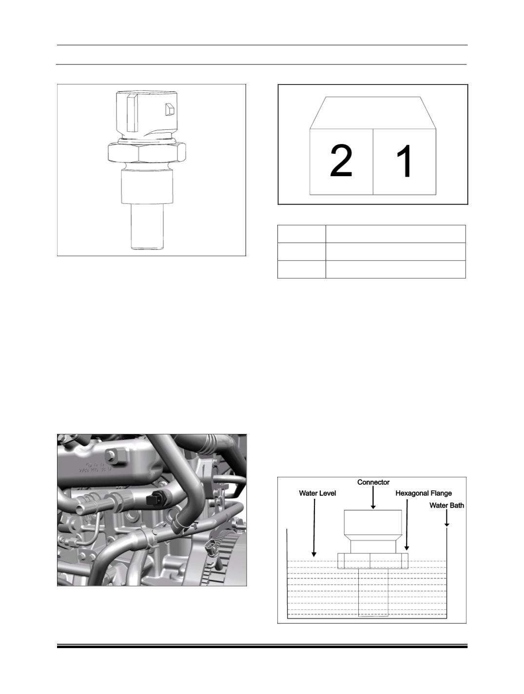
5. COOLANT TEMPERATURE SENSOR
This sensor is a made of semi conductor material
(
NTC
) which changes its resistance when exposed
to variable temperature source. Resistance de-
creases as temperature increases. There are two
temp sensors fitted on engine cooling circuit. The
sensor mounted on the upper cooling line is fitted
only in vehicles with manual HVAC and is not fitted
for vehicles with FATC. It provides temperature
signal to the HVAC controller. The sensor mounted
on the outlet elbow provides signal to the EMS. Cor-
rections for injection parameters are done by the
EMS based on coolant temperature to run the en-
gine with maximum efficiency at all temperatures.
LOCATION
1. The sensor which gives signal to EMS is fitted
on upper cooling line.
NOTE
Vehicles fitted with FATC do not need an additional
sensor as it receives the coolant temperature infor-
mation from CAN.
CONNECTOR DETAILS
PIN DETAILS
PIN NO DESCRIPTION
1
Sensor signal
2
Sensor return
REMOVAL
1. Remove the engine cover.
2. Drain the coolant. (
Refer Engine Section
)
3. Disconnect the wiring harness connector from
the sensor.
4. Loosen and remove sensor from the upper cool-
ing line.
INSPECTION
EQUIPMENTS REQUIRED
3 ½ Digital Multi-meter (
DMM
)
Water Bath
Heating arrangement for boiling the water
Measurement Set-up showing the water level up to
which the sensor should be dipped.