


 1640 / 1906

ELECTRICAL
338
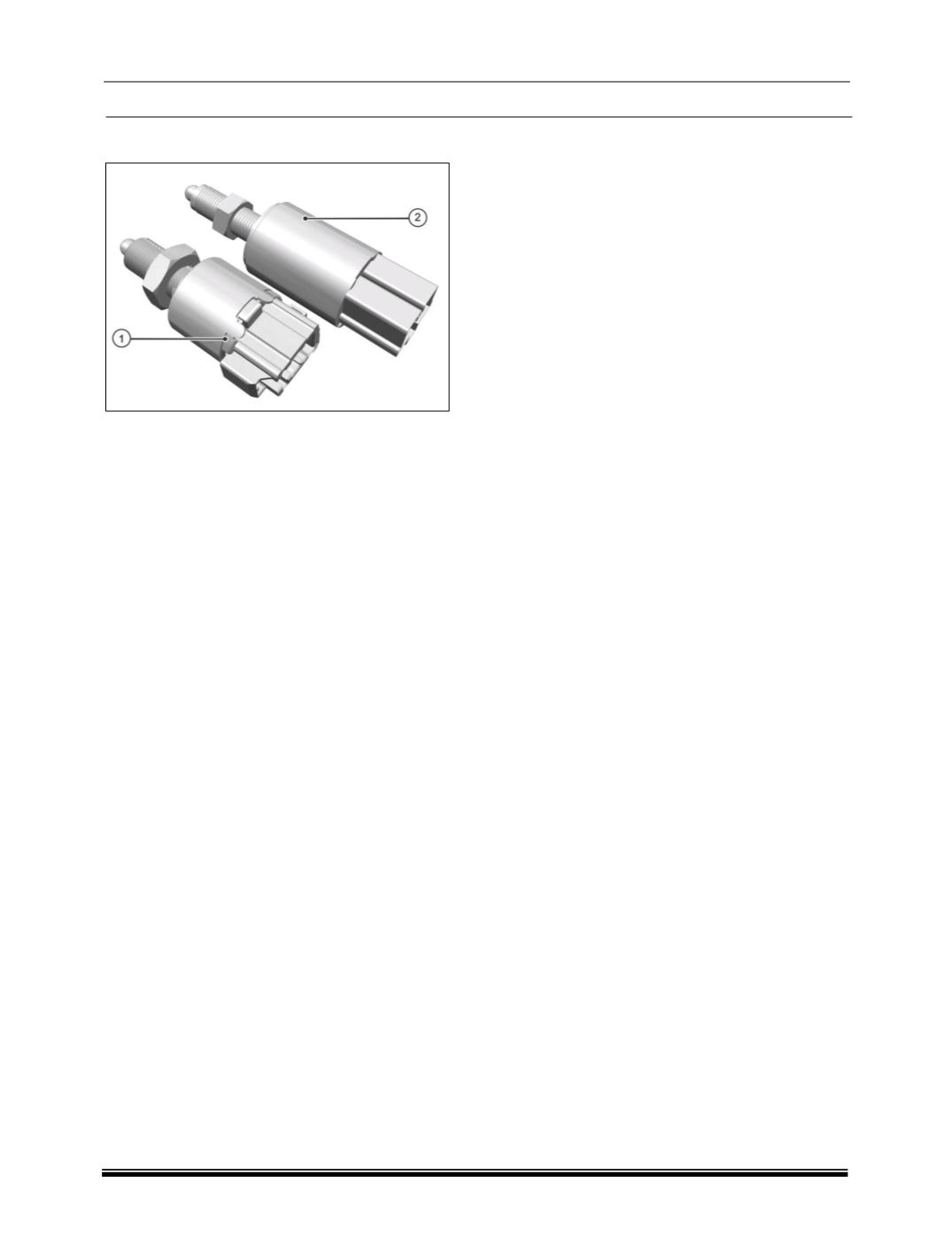
BRAKE SWITCH
The brake pedal is fitted with two Brake switches,
which provide the information to ECU about the
brake pedal application.
• Upper brake switch give signal to EMS ECU for
cruise control functionality.
• Lower brake switch give signal to tail lamp&
ABS/ESP ECU.
NOTE
In case of DTCs related to brake switch in
EMS ECU, Brake switch operation can be
checked using Diagnostics tool.
'Safety (Redundant) switch' should turn ON
first and then 'Main brake light switch'.
There is very little difference in operation of
these two brake switches, hence need to
checked carefully.
(Select 'Switch Test' subsection from drop
down menu of Vehicle parameters in EMS
ECU).
LOCATION
Brake switches are fitted on brake light switch
mounting bracket.
REMOVAL
Disconnect electrical connections of brake light
switch (1) and safety (Redundant) switch (2) (If
fitted).
Loosen the mounting nut of brake switch and take
out the brake switch by rotating anticlockwise
direction.
INSPECTION
Disconnect the connector and check the
continuity between the following pins. When the
pedal is depressed there should be connectivity
and when it is released to rest position there
should not be connectivity.
Brake Light Switch:
Pins 1 and 2 for Brake light circuit.
Pins 3 and 4 for Brake signal to EMS circuit
Brake switch for Cruise
Pins 1 and 3 for Brake pedal signal for cruise
control.
For switch adjustment details, refer brake section.
REFITMENT
1. Fit the brake light switch on the mounting
bracket and tighten its mounting nut.
NOTE
Refer brake section for brake switch adjustment
details.