


 1540 / 1906

ELECTRICAL
238
8.14.3
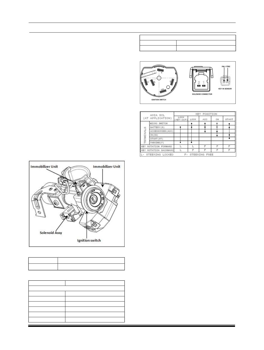
IGNITION
SWITCH_AT
WITH
IMMOBILIZER CAN VERSION PLUS KEY
RING ILLUMINATION (XMA, XTA):
x
LOCK – Steering Locked
x
ACC – All electrically Accessories ‘ON’
x
ON –IGNITION ON, RUN STATE
x
START – Engine Crank
IMMOBILIZER FUNCTION: (For Details refer
immobilizer section).
KEY IN SENSOR: Give signal regarding the key
status.
SOLENOID ASSY:
1). Rotation of the key from ACC to LOCK position
should be possible when the gear shift knob is at
park position. (Solenoid coil in de energized state;
ignition key can be taken out from Lock position).
2). Insert the key in lock position and rotate the
key from LockÆACCÆONÆSTART; when the
gear shift knob moved from park to drive mode
(Solenoid coil gets energized
).
SOLENOID
:
PIN 1
TERMINAL (-)VE
PIN 2
TERMINAL (+)VE
PINOUT DETAILS:
PIN NO
DESCRIPTION
IGNITION KEY
KA
KEY IN SENSOR
B
BATTERY
ACC
ACCEASSORIES
IG
IGNITION ON
ST
START
P
PA
KEY IN SENSOR
PIN 1
SUPPLY
PIN 2
SIGNAL
CONNECTOR DETAILS:
CIRCUIT DIAGRAM
Note :
1. Warming of key blade is normal phenomena
in AT ignition switch key.
2. Noise from ignition switch is due to internal
solenoid, it is also a normal phenomenon.
3. User need to remove key slowly otherwise
key stuck feeling may occur.