


 1247 / 1906

ELECTRONIC STABILITY PROGRAM (ESP)
14
If surface of the sensor is cracked, dented or
chipped off.
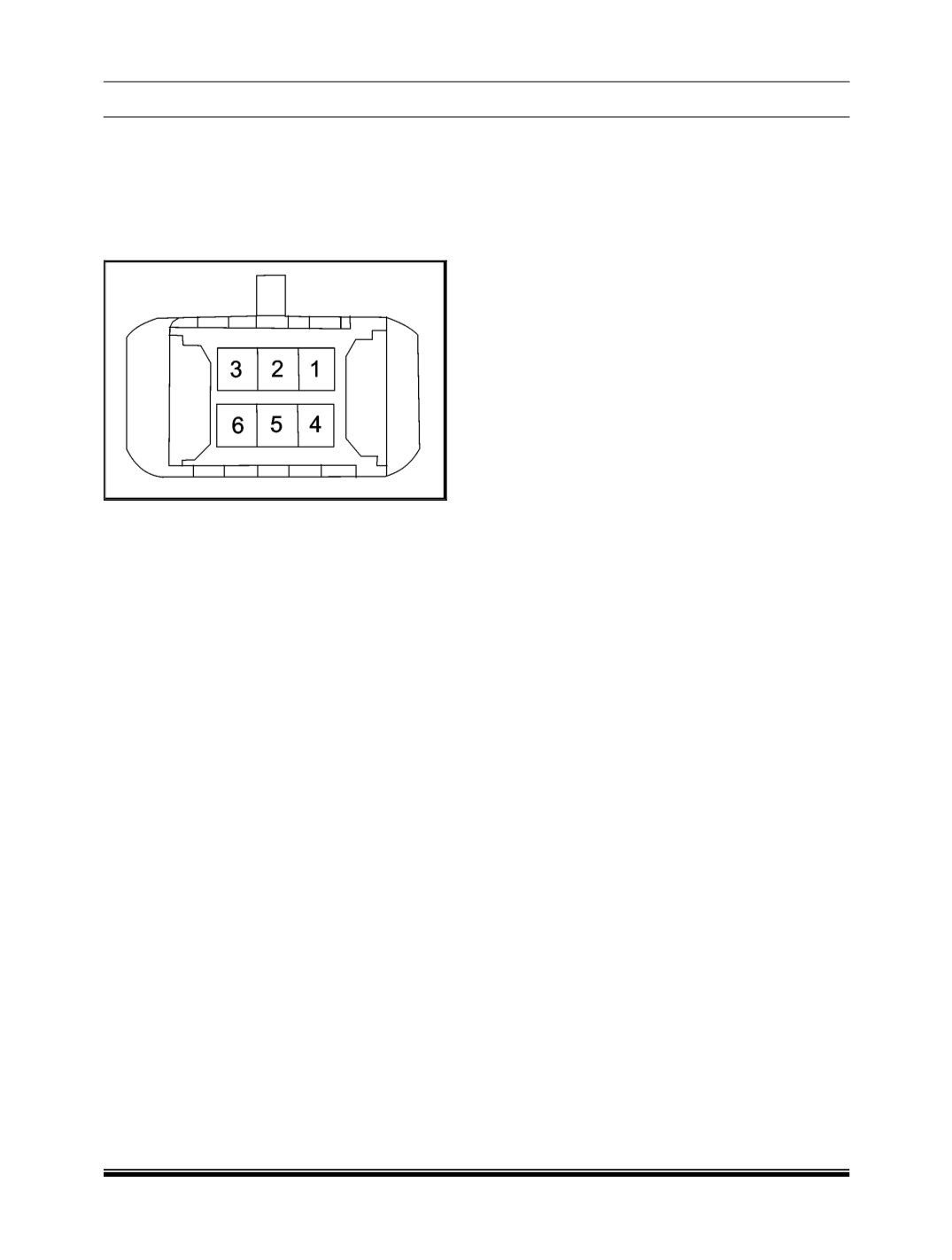
ELECTRICAL SUPPLY INSPECTION
1.
Disconnect the SAS electrical connector and
measure the voltage between pins 3 and 4 on
harness side connecter with Ignition ON.
2.
The voltage should be approximately 12V
(battery voltage).
If not then check the wiring
harness.
NOTE
SAS output can be checked using the diagnostic
tool in the SAS calibration option (Start Test) and
then clicking on ‘Steering Wheel Angle Position’.
REFITMENT
For refitment follow the reverse procedure of
removal.
First locate the locators.
Tighten the mounting screws to a torque of
0.03 Kg-m.
CAUTION
The steering angle sensor should be
calibrated when it is removed and refitted. If
this is not done the system may malfunction.
Refer ABS Diagnostic tool user manual for
details.
If proper locking between clock spring and
SAS is not there ESP might log faults.