


 1246 / 1906

ELECTRONIC STABILITY PROGRAM (ESP)
13
Electrical Supply Inspection:
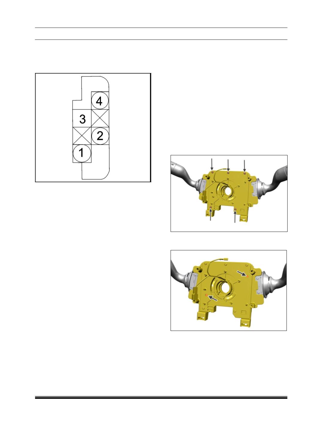
1.
Disconnect the YRS electrical connector and
measure the voltage between pins 1 and 4 on
harness side connecter with Ignition ON.
2.
The voltage should be approximately 12V
(battery voltage).
NOTE
YRS output, can be checked using the diagnostic
tool in the Dynamic Information option of
ABS/ESP diagnostic tester.
REFITMENT
For refitment follow the reverse procedure of
removal.
Tighten the mounting nuts to a torque of 0.4 –
0.6 Kg-m.
Clip the wiring properly to the bracket.
CAUTION
If Yaw Rate Sensor is not properly mounted or if
the screw tightening is not properly done, ESP
ECU might log faults
B. STEERING ANGLE SENSOR REMOVAL
1. Switch of the Ignition and disconnect the
battery.
2. Remove the steering wheel and its lower
cover.
(For procedures refer steering section).
3. Remove the upper and lower nacelle.
(For
procedure refer combi-switch removal in
Electrical section).
4. Disconnect all electrical connections to the
clock spring and Steering Angle Sensor.
5. Remove four mounting screws of clock spring
and take out the clock spring.
(Refer SRS
section).
6. Loosen and remove five mounting screws of
steering angle sensor.
7. Take out steering angle sensor from its
locators
.
INSPECTION
Inspect the steering angle sensor and replace
found in following conditions
If the connecter is damaged, scratched or
cracked.
If the sensor has been dropped.