


 417 / 1863

ENGINE
183
BRAKE LIGHT SWITCH
PIN NO DESCRIPTION
1
Ground
2
Ground
3
Clutch pedal signal to EMS
4
Clutch pedal signal to EMS
(Cruise
Control)
INSPECTION
Disconnect the connector and check the continuity
between the following pins. When the pedal is de-
pressed there should be connectivity and when
released to rest position there should not be con-
nectivity.
Pins 1 and 3 for Clutch pedal signal to EMS circuit
Pins 2 and 4 for Clutch pedal signal to EMS circuit
for cruise control.
REFITMENT
1. Fit the clutch light switch on the mounting brack-
et and tighten its mounting nut.
NOTE
Refer clutch section for clutch switch adjustment
details.
14. GLOW PLUGS
Glow plug is a pencil-shaped piece of metal with a
heating element at the tip, heats due to electrical
resistance and begins to emit light in the visible
spectrum, hence the term "glow" plug. The heat
generated by the glow plugs is directed into the cyl-
inders and serves to warm the engine block
immediately surrounding the cylinders. This aids in
reducing the amount of thermal diffusion which will
occur when the engine attempts to start.
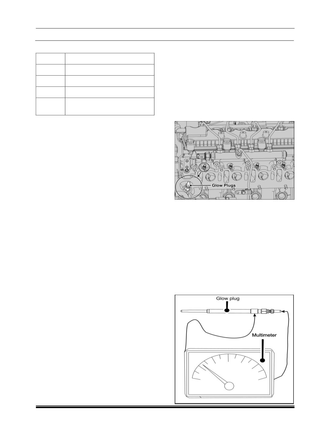
LOCATION
INSPECTION OF GLOW PLUGS
Check glow plugs for short circuits and or for burn-
ing. Replace them if necessary.
Testing of Glow Plugs
1. Clean the glow plugs.
2. Connect the electrodes of measuring device to
the glow plug as shown in below figure.
3. If the resistance value is around
∞
Ω the glow
plug is defective.
4. If the resistance Value is below
5Ω
, the glow
plug is Ok.