


 1850 / 1863

HVAC
79
23.11 COMPONENTS
SR. NO DESCRIPTION
SR. NO DESCRIPTION
01
Fully automatic control panel
04
Solar load sensor
02
Cockpit fuse & relay box
05
Incar sensor with integrated aspirator
A. HVAC Batt. - 5A
06
Ambient temp.sensor
B. HRW Fuse - 20A
07
Linear power module
C.Acc. Relay coil - 5A
08
Assy automatic front HVAC unit
D. PTC HRW coil - 10A
09
Thermister
03
Main Distribution Box
10
Mode & temp control actuator (
2 No’s
)
R5 - Heated rear window relay
11
Air inlet actuator
R6 - Air conditioning relay
12
Front blower motor
F05 - Accessories fuse 60 A
13
Assy trinary pressure switch
F12 – HVAC Fuse 40A
F14 – Aircon Fuse 15A
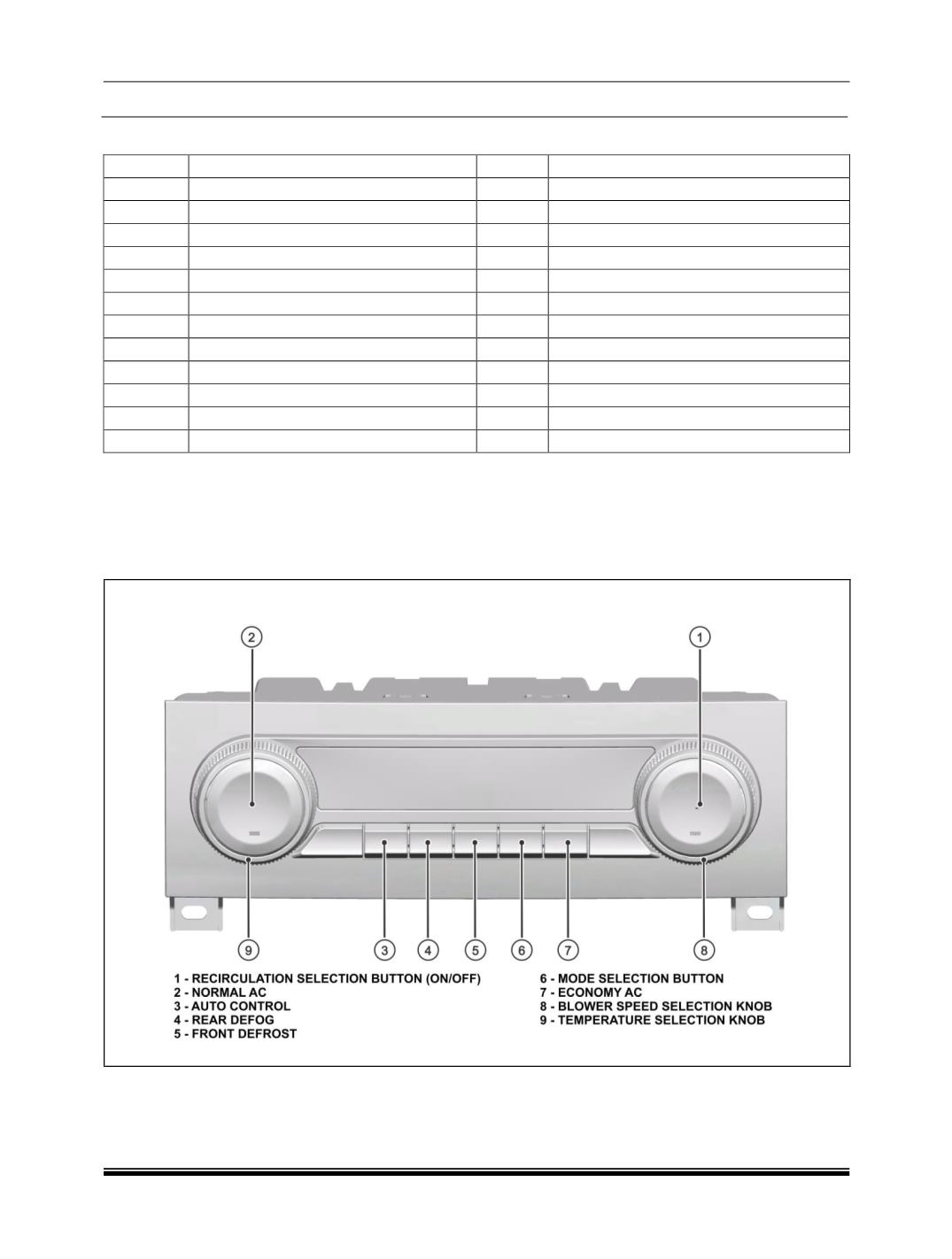
A. FATC CONTROL PANEL DETAILS
The climate control system is managed automatically by an electronic control unit known as the control panel
which has a built in algorithm to maintain the CCM settings, conditions set by the user. The FATC control panel is
a node of the CAN BUS.
The layout of the knobs and pushbuttons on the control panel are as below.