


 1822 / 1863

HVAC
51
23.7 ON VEHICLE REPAIRS
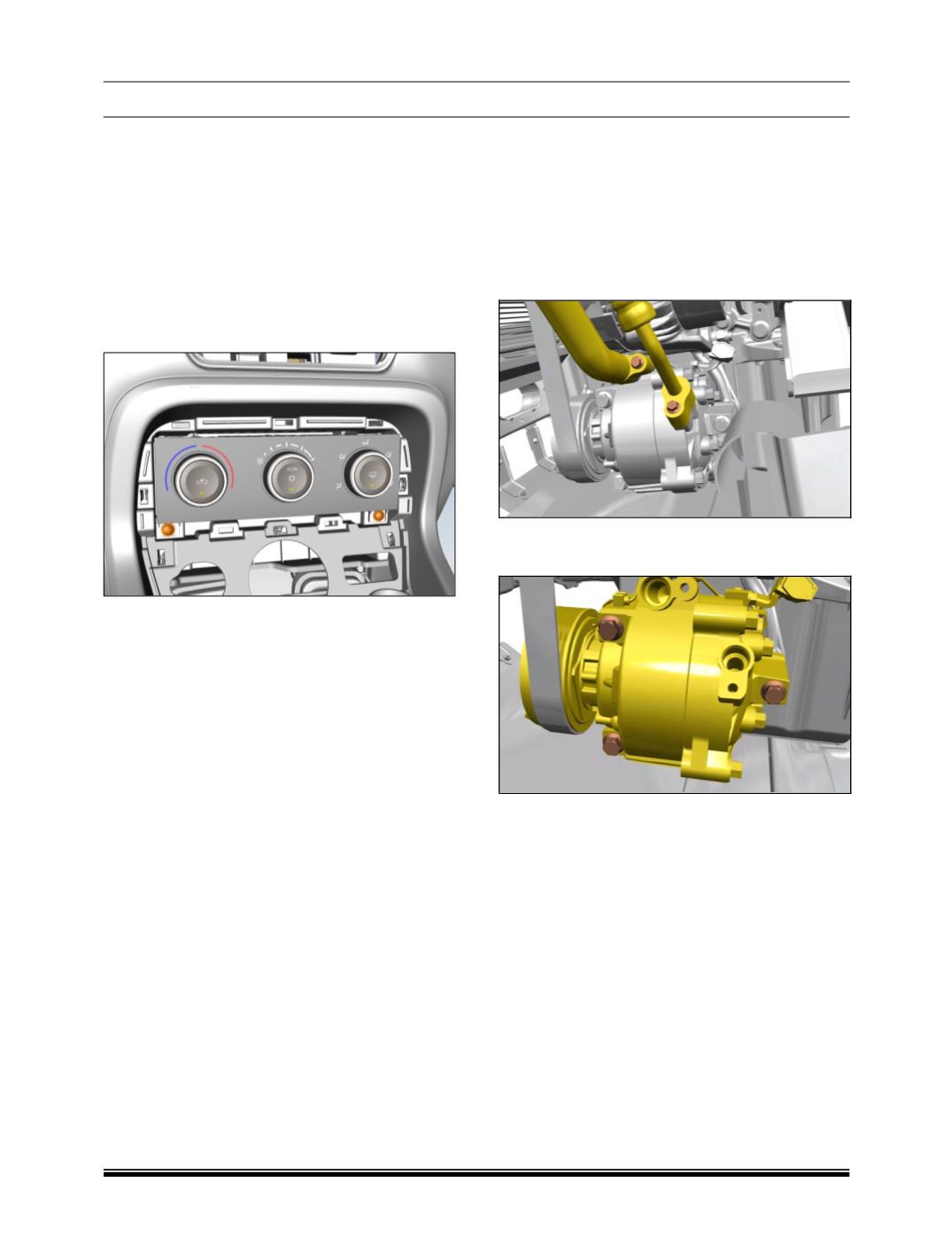
A. CONTROL PANEL ASSEMBLY
1. Refer Central console removal procedure from
body section for removal of the following compo-
nents:
a. Bottom bezel of cup holder.
b. Centre utility bin
c. cup holder
2. Loosen and remove the two screws.
3. Pull out the control panel to release the upper
mounting snaps.
4. Slowly pull out the control panel and disconnect
the two connectors.
B. COMPRESSOR REMOVAL
1. Discharge the refrigerant using standard recover-
ing equipment. Refer maintenance section.
2. Remove the AC Compressor belt; refer AC Com-
pressor belt removal procedure.
3. Disconnect the Suction line and the discharge
line.
4. Loosen and remove the mounting bolts and re-
move Compressor.
FITMENT
For fitment follow the reverse order of removal.
Tighten the following fasteners to the recommended
torque.
i) Compressor mounting.
ii) Refrigerant lines on compressor.