


 1797 / 1863

HVAC
26
INSPECTION
CALIBRATION CHECK
Every time the IGN is turned ON all the actuators will
travel to its end stops and come to rest at the desired
position selected in the control panel this is the cali-
bration that the system does. If this is not happening
then the system has to be calibrated as follows
1. Turn the IGN OFF and disconnect the battery.
2. Wait for approximately one minute and then re-
connect the battery.
3. Once the battery is connected again wait for one
minute and turn the IGN ON. Actuators are now
calibrated. Wait for one more minute after IGN is
turned ON until the actuators are calibrated.
Without removing the connector operate the respec-
tive knob and measure the voltage. The reading
should be as per the table below.
Motor Movement
V
DRIVE
Clockwise rotation (CW)
Mode: Defrost
Temperature: Full Cold
+4.9V
Counter Clockwise rotation (CCW)
Mode: Chest
Temperature: Full Hot
+0.5V
Maintain Position
+2.5V
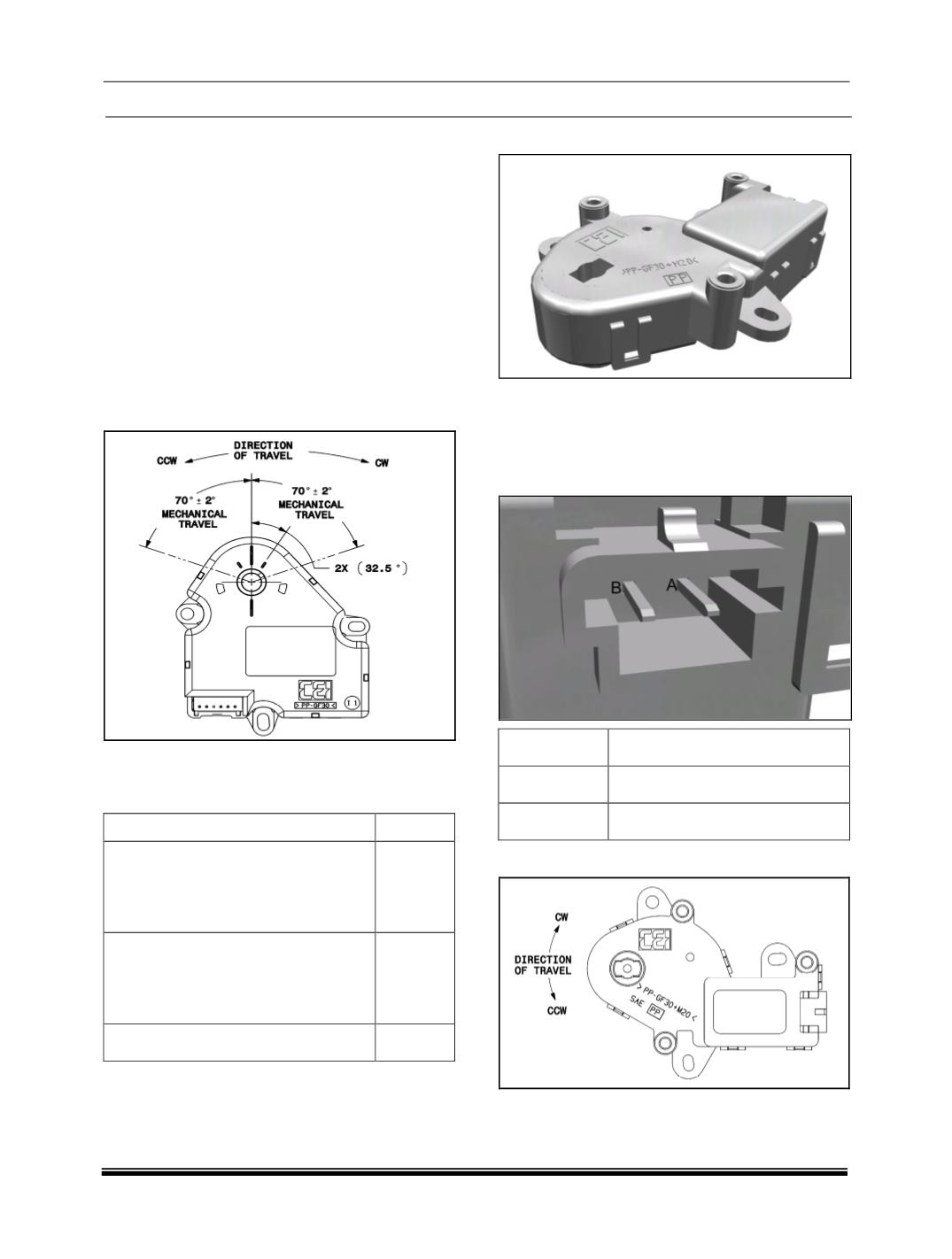
I. AIR INLET ACTUATOR.
The actuator used to operate the air intake door is a
bi-directional with no feedback actuator. It controls
the air intake door through the air intake control volt-
age.
PINOUT
PIN NO
DESCRIPTION
A (+)
Vs+
B (-)
GND
INSPECTION