


 697 / 1232

SUSPENSION
18
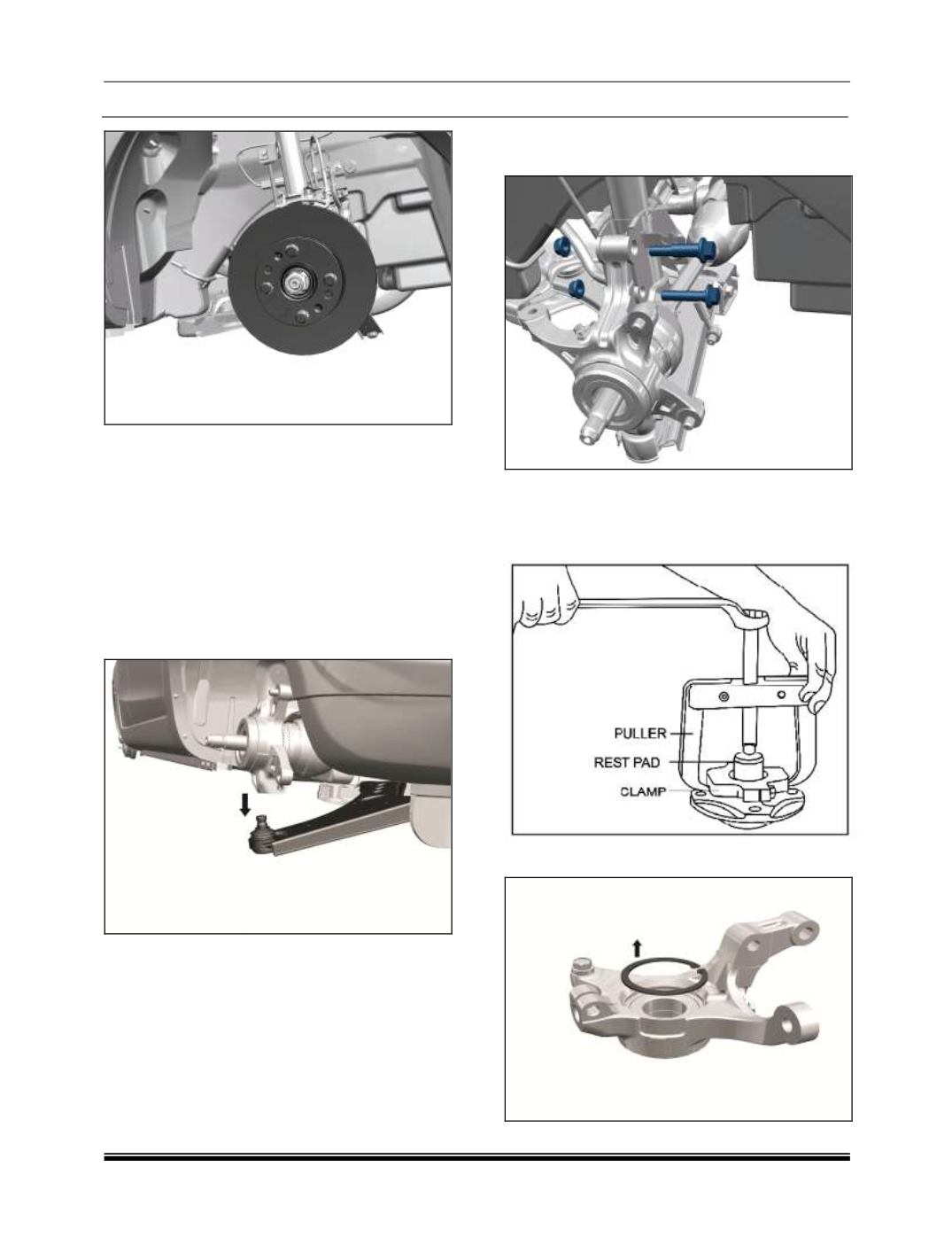
12. Unscrew the disc holding screws and remove
the disc.
13. Unscrew the sensor mounting screw and
remove the sensor (if applicable)
14. Pull out the hub with the help of puller part No.
2702 5890 3302 and striker part No. 2702
5890 3304
15. Remove puller from the hub.
16. Remove ball joint of lower arm from the
Knuckle.
17. Remove strut mounting bottom bolts from the
knuckle assembly by supporting the drive shaft
18. Using clamp part No. 2779 5890 3303 puller
part No. 2654 5890 3508 and rest part No.
2702 5890 2612 remove inner race of bearing
from the hub
19. Remove circlip from knuckle.