


 950 / 1236

ELECTRICAL
172
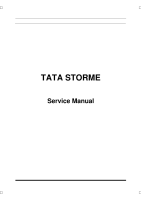
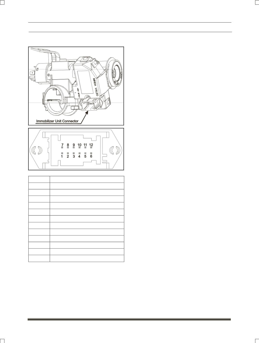
4. IMMOBILIZER CONNECTOR AND PINOUT
DETAILS:
5. IMMOBILIZER WORKING PRINCIPLE:
The EMS ECU and the immobilizer are
paired together by an encrypted secret code called
as “AES secret key”, to improve the security of the
vehicle. This AES secret key is generated using
the vehicle identification number (
VIN
) and it is
unique for each vehicle. Both immobilizer and the
EMS ECU are programmed with same secret key
for mutual authentication. If any one of EMS or ICU
has different/wrong secret key, vehicle will be
locked (
engine cannot be started
).
If EMS or Immobilizer is changed in a
vehicle, it is required pairing operation (
EMS ECU
and ICU programmed with same secret key
) for
proper mutual authentication. The pairing of EMS
and Immobilizer can be done through diagnostic
tester.
Immobilizer comes with two Electronic
keys (
E-key
). These E-keys are learned for that
immobilizer and are unique to that Immobilizer and
vehicle. The E-key of other vehicles will not work
with this immobilizer and vice versa.
If anyone of the E-key is lost, it is
recommended to approach authorized dealer for
new E-key. It is possible to learn new keys with the
help of diagnostic tester.
(Refer the key learning
procedure).
If both the keys are lost, it is not be
possible to learn the new keys for that immobilizer,
as original key is required during E-key learning
operation.
Immobilizer system status on Starting:
During Ignition off, immobilizer status lamp
(“
Lock” symbol on the instrument cluster
)
blinks, indicating Immobilizer is awaiting E-key.
When the ignition key is turned to the "ON"
position,
1. If the status lamp goes OFF indicates that
the system is working and the vehicle is
unlocked (
Engine is ready to start
).
2. If the status lamp is continuously ON, there
may be something wrong with key or with the
immobilizer system.
PIN NO DESCRIPTION
1
NC
2
K-line Diagnostics
3
CAN_H
4
GND
5
CAN_L
6
Battery
(+12V
)
7
NC
8
NC
9
Status Lamp (“
lock symbol
”) in cluster
10
NC
11
Light guide
12
Ignition
(+12V
)