


 956 / 1236

ELECTRICAL
178
12. IMMOBILIZER CAN DIAGNOSTIC:
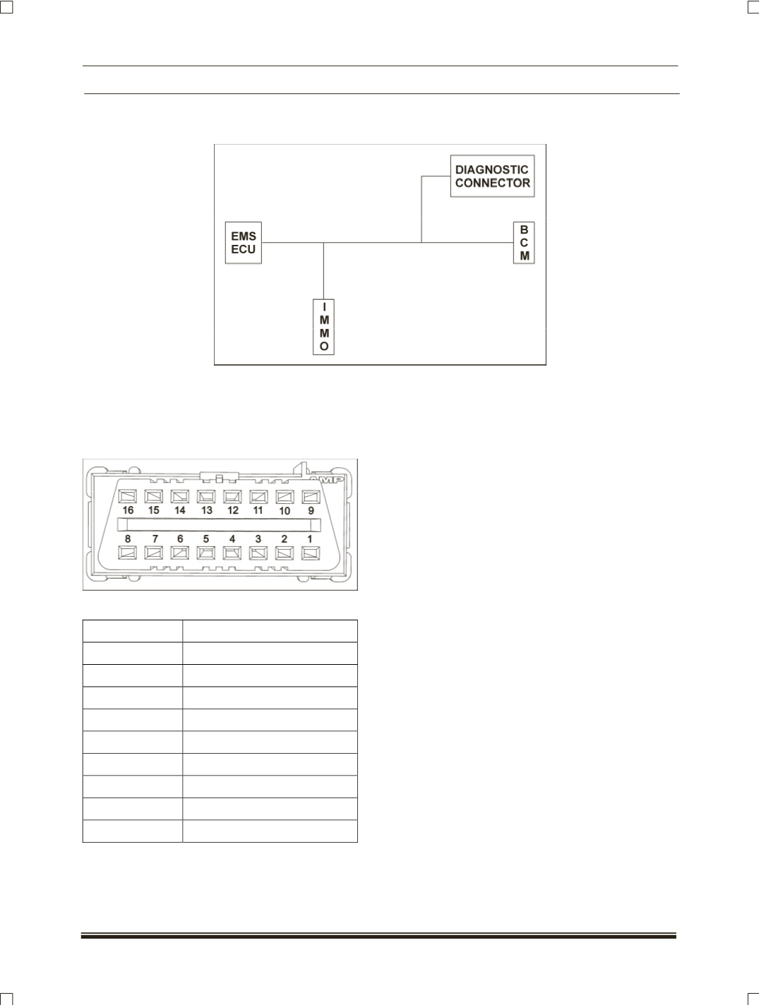
IMMOBILIZER CAN ARCHITECTURE
The immobilizer system uses a High Speed CAN to communicate the lock and unlock code from Immobilizer
control unit to EMS. The EMS ECU and the BCM act as the terminal resistors for this CAN. BCM is not
functionally connected but is only connected to terminate the CAN. There are 2 splices in the CAN, one for
Immobilizer and the other for the Diagnostic Connector.
DIAGNOSTIC CONNECTOR DETAILS:
PIN OUT DETAILS:
PIN NO.
DESCRIPTION
1-3
NC
4
GND
5
GND (CAN)
6
CAN H
7
K Line
8-13
NC
14
CAN L
15
NC
16
Batt.