


 91 / 1236

ENGINE
.
59
7. Remove the glow plugs.
INSPECTION
A. CYLINDER HEAD
CHECKINGCYLINDERHEAD MATING SURFACE:
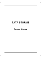
1. Using a straight edge and feeler gauge, check
evenness of cylinder head parting surface with
crank case. If unevenness exceeds specified
values, replace cylinder head.
2. Permissible unevenness of cylinder head mating
surface-0.030 mm
(Length wise)
3. Permissible unevenness of cylinder head mat-
ing surface-0.015 mm
(Cross wise)
NOTE
Cylinder head top and bottom surface re-machining
in service is not permitted.
B. VALVES
1. Check valve leakages by pouring gasoline on
valve head. Gasoline must not seep past valve
seat.
2. Valves with burnt heads, excessive scoring and
wear on stem should be replaced.
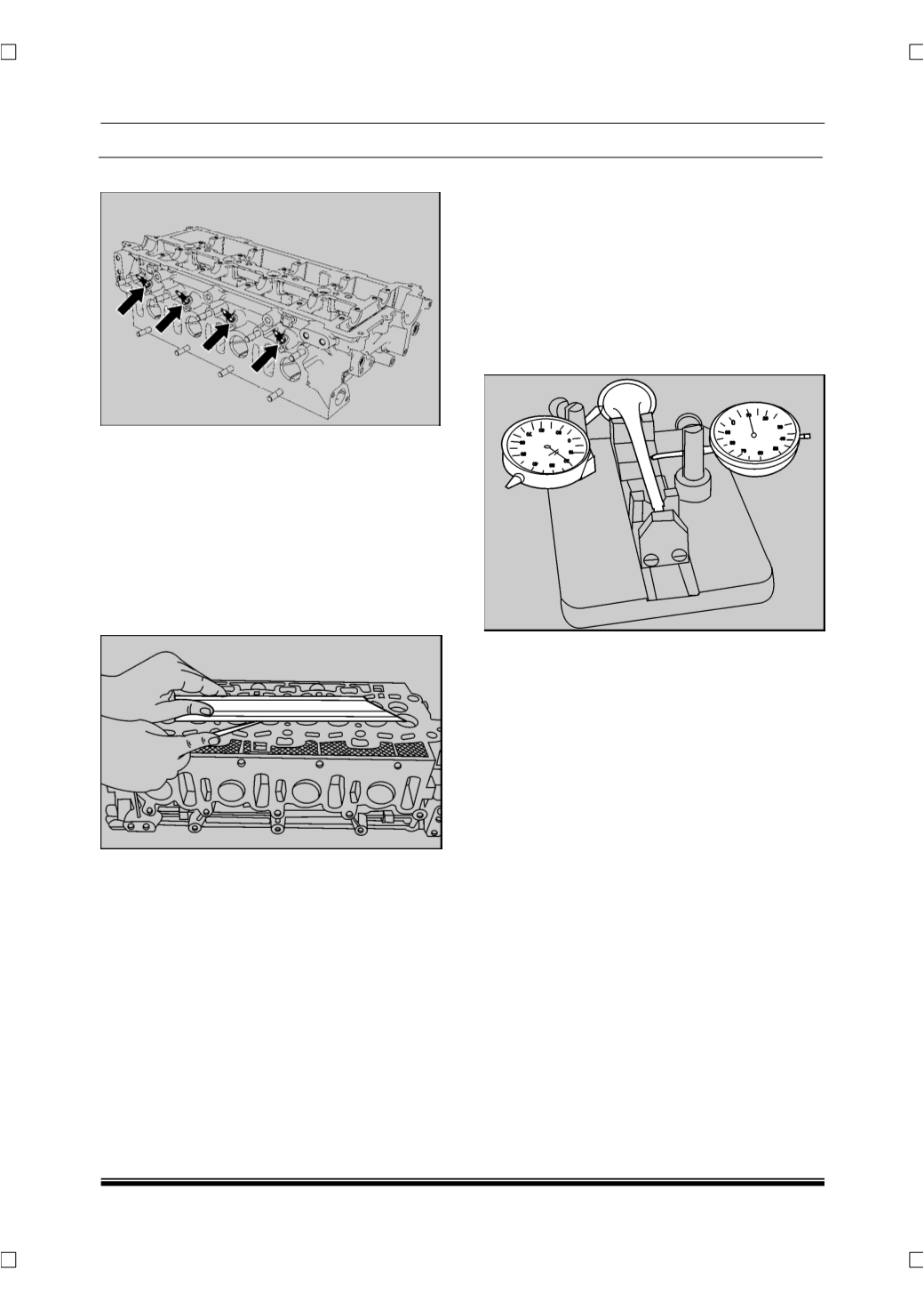
3. Check valve seat run out with respect to valve
stem. If it exceeds specified limit replace valve.
No attempt should be made to straighten bent
valves.
4. If valve is free from any other defects except
worn out seat, then only it can be rematched on
valve grinding machine as follows:
•
Clamp valve on grinding machine jaws as
close as possible to valve head.
•
Adjust grinding angle on graduated scale to
achieve correct valve seat angle.
•
Feed valve slowly towards grinding wheel until
wheel just touches valve head.
•
Grind at low feed until valve seat is just clean
all around.
NOTE:
After grinding, valve head thickness should not be
less than 0.85 mm.