


 866 / 1236

ELECTRICAL
88
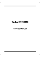
REMOVAL:
1. Remove the combi-switch. (
Refer combi switch
section
).
2. Disconnect the electrical connection of ignition
Switch, immobilizer unit and key-in sensor.
3.Break heads of two mounting bolts (
self breaking
type screws
) with the help of chisel.
4.Take out the assembly from its locating latch.
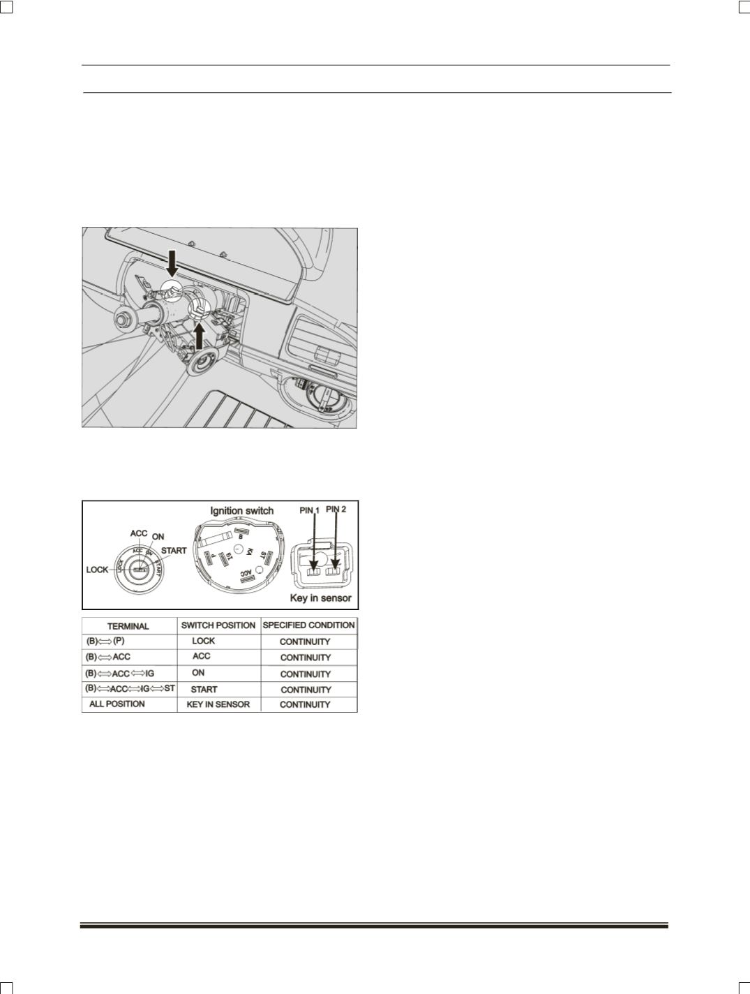
INSPECTION:
Inspect the switch continuity.
If result is not as per specified, then replace the
switch assembly.
REFITMENT:
1.Disassemble the mounting bracket of new
ignition switch.
2.Locate the ignition switch to steering column
cutout with latch lock. (
Refer fitment details
image)
.
3.Tighten the ignition switch to steering column
with the two self breaking screws.
Tightening Torque for screws – 1.5 Kgm
NOTE:
There should not be any rotary movement of the
lock on column when fully tightened as specified
4.Connect the electrical connection of ignition
Switch, immobilizer unit and key in sensor.
5.Fit the combi switch assembly.