


 862 / 1236

ELECTRICAL
84
REMOVAL:
1.Remove the steering wheel (
For procedure refer
steering section
).
2.Loosen three fixing screws of assy nacelle lower
and assy nacelle upper, located in bottom side of
assy nacelle lower.
3.Dismantle both nacelle from snap fitting and take
out the both nacelle.
4.Disconnect the all connectors of combi-switch, &
clock spring.
5.Remove the clock spring (
if fitted
) (For
procedures refer SRS section
).
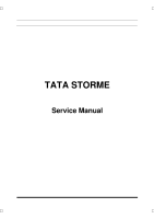
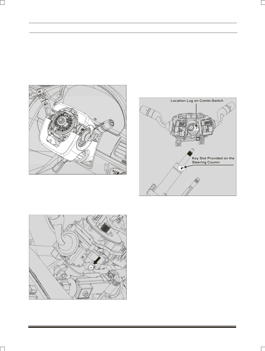
6.Loosen one mounting screw of combi-switch and
pull out the combi-switch assembly.
INSPECTION:
1. Disconnect the Combi - switch connectors.
2. Using multimeter, check the continuity or
resistance values between the terminals
according to switch position. If continuity not
found, replace the effective stalk.
REFITMENT:
1.Insert the combi-switch assembly into the
steering column and aligned the location lug with
the key slot provided on steering column.
2.Tighten the one mounting screw of combi-switch
Tightening torque for the screw – 0.18 Kgm.
NOTE:
There should not be any lateral movement.
There should not be any damage or
deformation observed on the combi switch
housing and the mounting screw.
3.Fit the clock spring (
If fitted
) (
For procedure refer
SRS section
).
4.Connect all the connectors of combi-switch, &
clock spring.
5.Snap fit the assy lower nacelle and assy upper
nacelle, and fit the three mounting screws in the
assy nacelle lower.
6.Fit the steering wheel properly. (
For procedure
refer steering section
).