


 933 / 1526

77
ENGINE2.2LDICOR
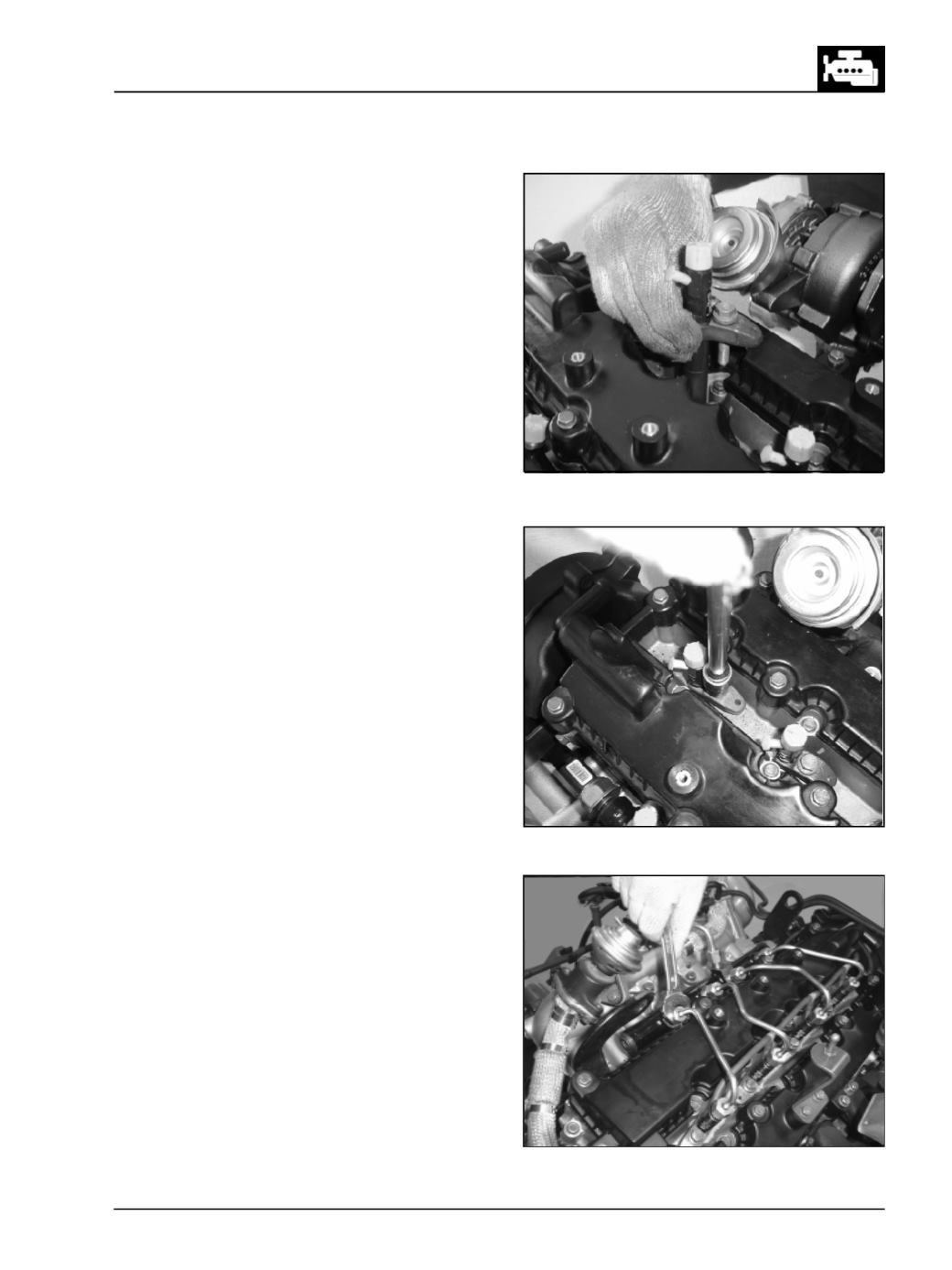
Fig. 188
Fig. 189
Fig. 190
l
Install all injector & mounting claw assemblies.
(Fig. 188)
l
Note down the cylinder numbers & respective
injectors C2I values.
l
Tighten the injector mounting claws to specified
torque. (Fig. 189)
l
Remove the caps & Assemble all the HP lines
between common rail & injectors respectively (Fig.
190 & 191)