


 734 / 1526

27
BODY
l
Connect electrical components' connectors to
wiring harness properly. If necessary pull out the
required portion of plastic membrane and fix it
after completing the electrical connections. Refer
electrical group for wiring harness tail gate.
l
Fix the wiring harness clamps on the door
properly.
l
Removeplugandconnect rearwindowwasher tube.
l
Fit the tail gate inner trims. Refer “Removal/
Installation of tail gate inner trims”.
l
Close the tail gate.
l
Fit the spare wheel.
Note :
For tail gate adjustment, loosen the hingemounting
screws on body. Align and adjust the tail gate
properly and tighten the mounting screws.
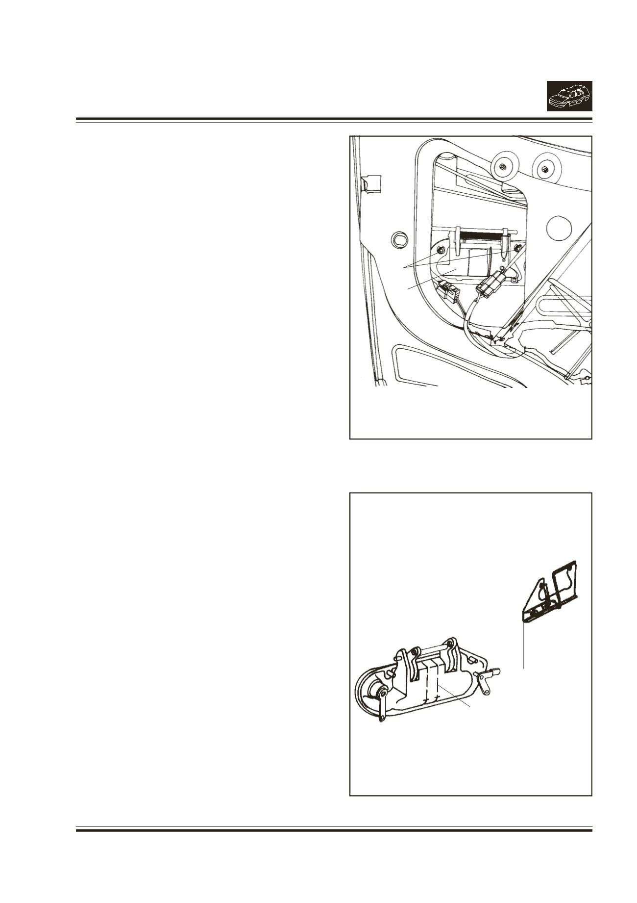
7. REMOVAL/INSTALLATION OF DOOR OUTER
HANDLE
(Fig. 7 & 8)
REMOVAL
l
Remove the inner trim.
l
Pull out required portion of plastic membrane.
l
Disconnect links from outer handle.
l
Remove 2 mounting flanged nuts.
l
Remove handle by disengaging the snaps
properly.
INSTALLATION
l
Locate outer handle on door panel. Install 2
flanged nuts (M6).Tighten nuts after ensuring the
snaps properly.
l
Connect links to outer handle properly.
l
Ensure handle functions properly.
l
Apply sealant (Butyl mastic) on the door inner
panel and fix the plastic membrane on it.
l
Fit the inner trim.
Note :
Do not disturb the adjustment of door handle link
and door lock link. If disturbed readjust and ensure
proper functioning of door handle and door lock.
Fig. 7.
1.
MOUNTING NUTS OF OUTER HANDLE
2.
OUTERHANDLE
1
2
Fig. 8.
1.
OUTERHANDLE
2.
LINKOUTER HANDLE
1
2