


 730 / 1526

23
BODY
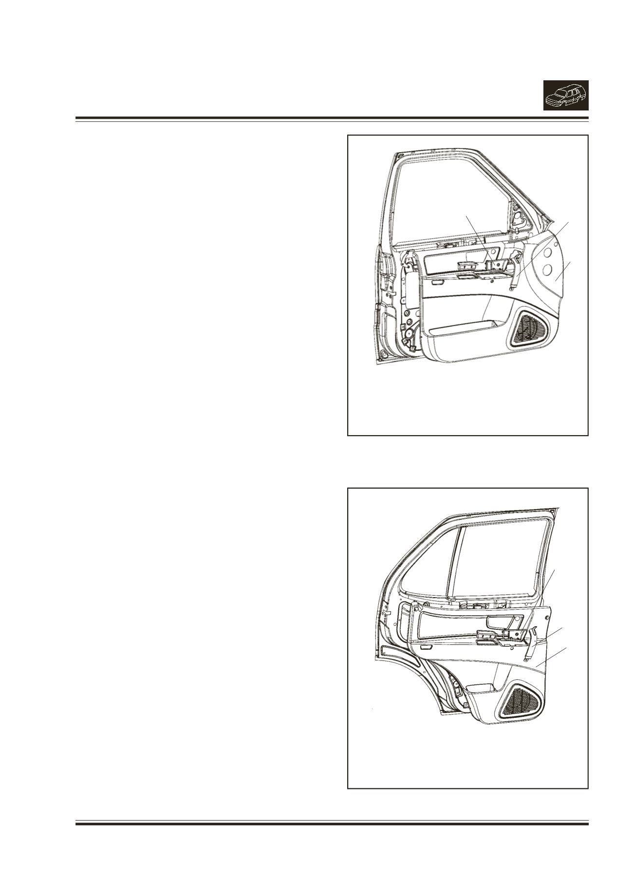
3. REMOVAL/INSTALLATION OF FRONT/REAR
DOOR INNERTRIM
(Fig. 1 & 2)
REMOVAL
Note :
Disconnect battery before doing repair work
on the body.
l
Open the door.
l
Remove 2 mounting screws of door pull and
remove the door pull.
l
Remove themounting screw of inner handle cover
and door pull. Remove the cover and door pull.
l
Remove the decorative caps at the top 1 No. for
front and 2 No. for rear door and remove 3
mounting screws viz. 1 at side and 2 at bottom
for front door. (3 at side and 2 at bottom for rear
door trim)
l
Pull out the door trim halfway and disconnect
power window switch connector, speaker
connector and cour tesy lamp connector.
Disconnect mirror switch connector for driver door.
l
Remove the trim.
INSTALLATION
l
Replace the trim fixing clips.
l
Locate the trim on the door.
l
Connect courtesy lamp connector and power
window switch connector to speaker connector
wiring harness. Connect mirror switch connector
for driver door.
l
Ensure that 7 trim clips are properly located in
mounting holes for front door (6 trim clips for rear
door).
l
Press the trim on the door properly.
l
Fit the (door pull) using 2 sl. ch. screws and
tighten the screws.
l
Fit the cover of inner door handle with cr pan hd
screw M6x16.
l
Fix decorative caps. (1 for Front & 2 for Rear
Door Trim)
Fig. 1 - Front Door
Fig. 2 - Rear Door
1
2
3
1.
INNER HANDLE COVER
2.
DOOR PULL
3.
DOOR INNER TRIM
1
2
1.
INNER HANDLE COVER
2.
DOOR PULL
3.
DOOR INNER TRIM
3