


 524 / 1526

49
BRAKES
PARKING BRAKE
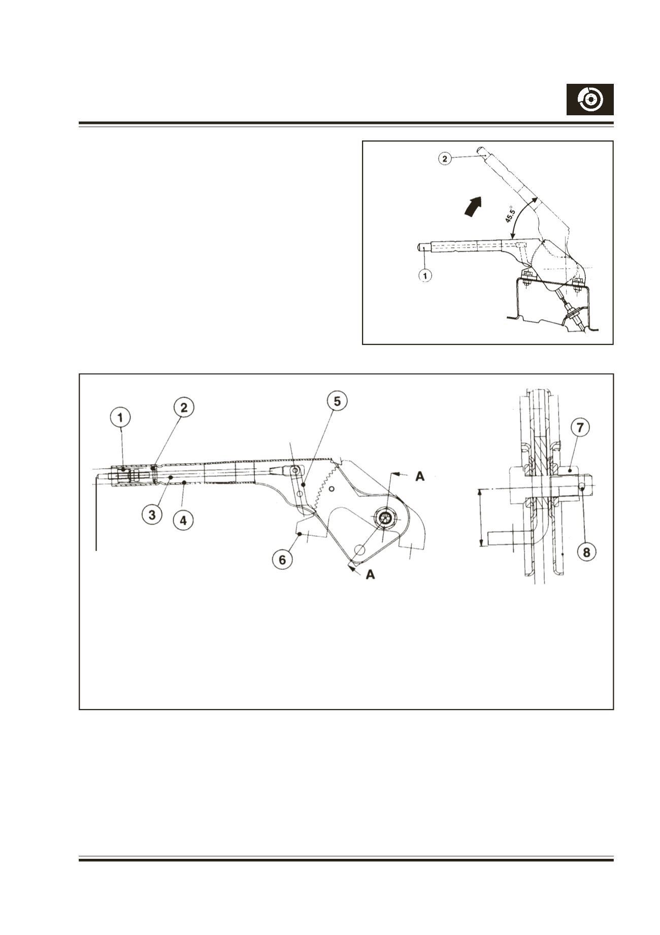
Fig.50
The parking brake arrangement is a cable operated
system, acting on the rear wheels. It is operated by a
handle situated in the cab.When the handle is pulled
up, the parking brake lever inside the rear drumbrakes
is also pulled through the cable system. This action
expands the rear brake shoes against the drum, thus
applying the rear brakes.
Fig. 50 - Parking brake handle
1. Parking brake released
2. Parking brake applied
1. COIL SPRING
2. SLEEVE
3. PAWL ROD
4. LEVER
5. PAWL
6. RATCHET
7. CASTLE NUT
8. SPLIT PIN
SECTION - AA
Fig.51- Parking Brake Lever Construction
NOTE:
LATERAL PLAY AT FULCRUM TO BE MINIMUM POSSIBLE
(0.125 MM MAX.)
TO ADJUST THIS PLAY, TIGHTEN THE CASTLE NUT FULLY,
LOOSEN THE NUT TO MINIMUM EXTENT TILL THE HANDLE
IS FREE TO MOVE, ENGAGE THE SPLIT PIN AT THE NEAREST
HOLE ON THE BOLT AND BEND THE SPLIT PIN.
This is a safety device so that the parking brake does
not get released accidently.
To release parking brake, the lever is to be lifted
slightly and keeping button pressed, lever is to be
pushed down fully. When button is pushed as above,
pawl rod also get pushed, disengaging pawl from
ratchet, thus releasing the parking brake.
(30 mm)
BUTTON/KNOB