


 513 / 1526

38
BRAKES
1.
FUNCTION :
To provide power assistance by boosting up
mechanical effort applied at the brake pedal
on the hydraulic master cylinder attached to it,
using vacuum. The vacuum brake valve
operates on the pressure difference between
vacuum and atmospheric air.
2.
DESCRIPTION (Fig. 41):
This assembly is installed between the brake
pedal and the master cylinder. Employing the
pressure difference between the vacuum
developed by the vacuum pump and
atmospheric pressure, the vacuum brake valve
amplifies the input force on the brake pedal
resulting in more effective braking
performance. The servomechanism, which
converts this input force into braking force, is
a rubber reaction disc type balancing system.
3.
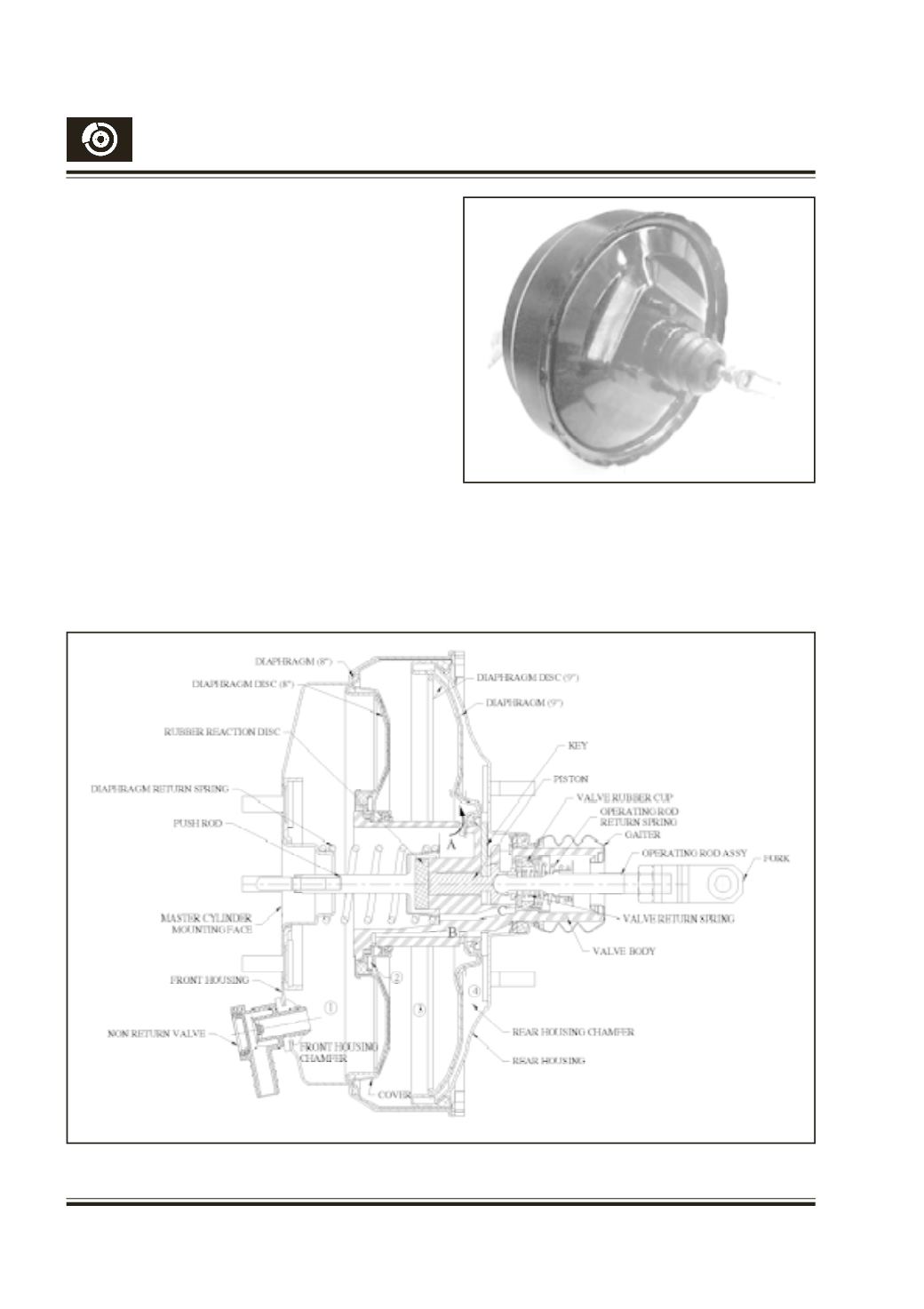
CONSTRUCTION (Fig. 41 & 42):
The assembly mainly consists of two
diaphragms, sheet metal pressed front and
rear housings, cover, valve body, operating rod
Fig. 41
Fig. 42
assembly, push rod, key and rubber reaction
disc. The 9” diaphragm’s outer bead is clamped
between the front and rear housing and its inner
bead is mounted on the valve body. The 8”
diaphragm’s outer bead is clamped between
front housing and cover and its inner bead is