


 515 / 1526

40
BRAKES
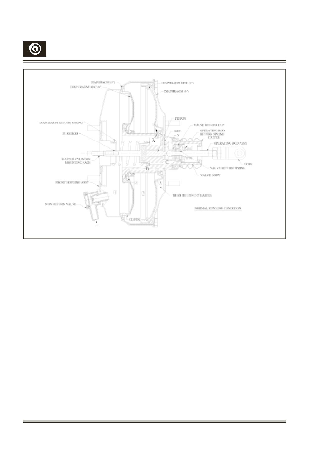
Fig. 44
5.
OPERATION:
5.1 Released or normal running position (Fig. 44) :
When the brakes are released, the vacuumbrake
valve is in released position. The valve body,
operating rod sub-assembly, diaphragms and
diaphragm discs are positioned towards the rear
housing side due to the fitted load of diaphragm
return spring. Both the vacuum valve (X) and air
valve (Y) are in closed condition. Vacuum is
applied to the vacuum brake valve, through the
non-return valve in the front housing.Vacuum is
communicated from chamber 1 to chamber 3
through the passage A and to chamber 4 through
vacuum passage C. From chamber 4, vacuum
is communicated to chamber 2 through the
passage B. There is constant vacuum in all the
4 chambers, in the normal running condition. As
the diaphragms and valve body are pushed
towards rear housing by the diaphragm return
spring, no force is transmitted to the master
cylinder in this condition.
TO VACUUM