


 508 / 1526

33
BRAKES
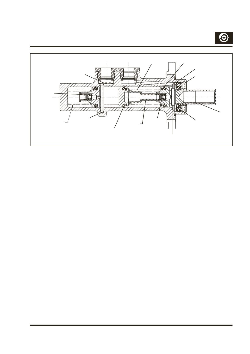
Fig. 34 CV / CV Tandom Master Cylinder for ABS
PRIMARY
GLAND SEAL
incase of any failure / malfunction the entire
Tandem Master cylinder assy. to be replaced.
Working principle :
In the normal “Brakes-off” position, the brake fluid can
flow unrestricted between the dual line systems and
separate chambers in the integral fluid reservoir. Fluid
movement to the independent cylinders is controlled
by
Two valves - (center valves).
Hence it is called
CV/CV master cylinder Ref Fig. 34
When the brake is applied the push rod pushes master
cylinder primary plunger of the bore. This master
cylinder is divided into two chambers. The primary
train is composite assembly and is resting on stop
washer through a connecting pin.
Connecting pin is rectangular in section and has a
hole at center. One end of the valve stem passes
through this hole. The connecting pin is assembled
in to the circular hole on primary plunger as shown
in Fig. 34
The poppet valve train consists of poppet valve
assembled on the valve stem. This composite
assembly is ahead upon by a valve spring. The end
of the valve spring is resting on the distance sleeve.
The distance sleeve is held rigidly with the plunger
by 6 or 8 crimps on the plunger.
A similar arrangement is provided for secondary
train also. The secondary plunger has a center slot
into which the stop pin reciprocates. A cover plate
is assembled in-between the scondary grommet and
connecting pin to prevent falling off of connecting pin
from cylinder body. This plate also acts as a baffle
and reduces the velocity of fluid jet that will emerge
from secondary feed ports on return.
Secondary and primary plunger train moves as a
composite assembly. At this juncture the poppet
valve (centre valves) of both primary and secondary
closes the respective sealing faces of the plunger
and pressure is developed.
During further stroke of the primary plunger, the
primary springs cmopressed and pressure is
developed. The pressurized fluid is forced though
pipelines to the calipers and wheel cylinders.
When the brake is released, the master cylinder
plungers move back creating partial vacuum in front
of poppet valves (center valves) deseating by
deflecting poppet spring and the port are opened
and the brake fluid can again move unrestricted
between separate systems and the fluid reservoir.
Servicing :
The master cylinder is not serviceable
After every 40,000 kms/24000 miles or 2 years,
whichever occurs first, the master cylinder should be
replaced with genuine master cylinder assy.
WASHER
(RETAINING)
RETAINER
SPRING
(POPPET)
STOP PIN
SLEEVE
SECONDARY
GLAND SEAL
POPPET
VALVE
ASSY
CONNECTING
PIN
SPRING
RETAINER
RECUPERATING
SEAL (PRIMARY)
STOP WASHER
CIRCLIP
PRIMARY
PLUNGER