


 499 / 1526

24
BRAKES
lever (18) and rotating the serrated adjuster nut (11).
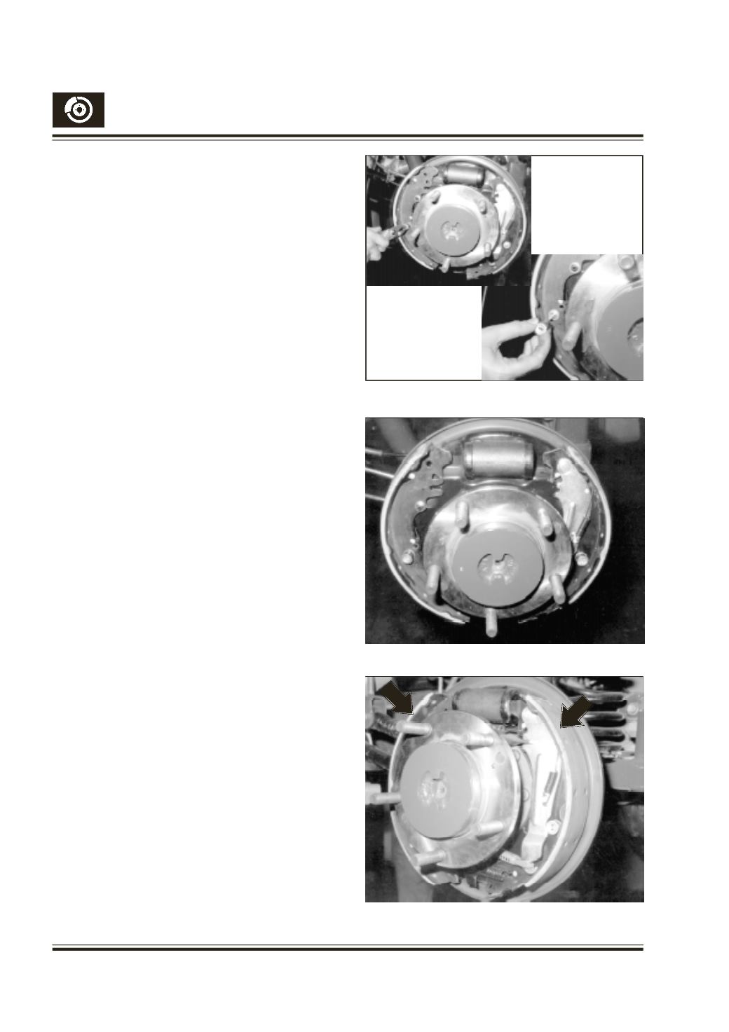
Taking care not to damage the rubber dust covers
(25) on the wheel cylinder body (30), slide both shoes
(2 & 3) off the wheel cylinder pistons. Fig. 22
Manipulate the shoes to detach the adjuster assembly
and shoe return spring (8).
Remove shoe hold down springs (6) and cup washers
(5) from the back plate by compressing the spring (6).
Fig. 23
INSPECTION
Observe for wheel cylinder leak by lifting the rubber
dust covers (25) on the cylinder. If leak is observed
replacement of kit is recommended. If no leak is
observed, check the pistons (26) for freedom of
movement and temporarily fit an elastic band around
the cylinder to retain the pistons in the bore.
CLEANING
Clean the backplate thoroughly. Use a wire brush to
remove any corrosion, but take care not to damage
the rubber dust covers on the wheel cylinder.
Note : Never use petrol or kerosene, or paraffin
etc. for cleaning brake parts as they are
dangerous.
Ensure shoe-sliding platforms on the backplate (1)
are smooth and not corroded. If necessary, Clean the
filings and apply a light smear of Graphite grease (high
melting point grease) to each platform. Fig. 24
Examine the adjuster assembly to see it is in good
working order and ensure the adjuster nut is free to
run the full length of the thread. Care must be taken to
fit left and right hand thread nuts properly.
RELININGTHE SHOES (
Fig. 25)
Inspect the linings. Linings should not be allowed to
wear down to the rivet heads. If the linings are worn
down to 0.5 mm above the rivet head they must be
replaced. Derivet them carefully. Before deriveting,
detach the hand brake operating lever from the trailing
shoe. This may be done as follows:
Remove retaining plate from the pin groove by sliding
with a screw driver. Remove spring plate. Lightly tap
the pin to remove the operating lever from the shoe. If
excessive wear on this pin is noticed, it should be
replaced.
Fig. 23
Fig.24
Fig. 25