


 1518 / 1526

29
BODY
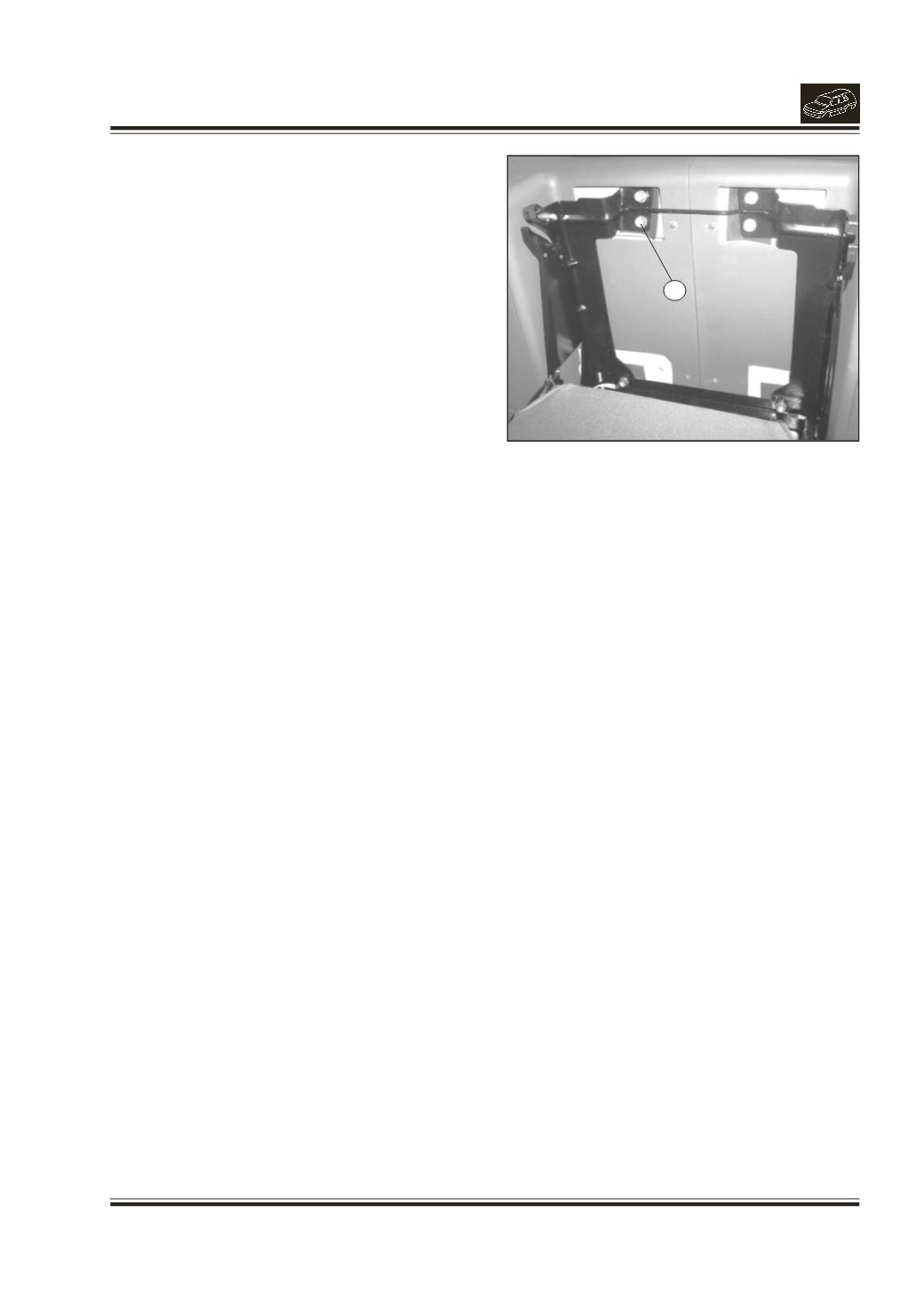
Fig. 26.
1. MOUNTING SCREWS
1
22. REMOVAL/INSTALLATION OF JUMP SEAT
(if
fitted) (Fig. 26)
REMOVAL
l
Take down the jump seat RH by lifting up and
pulling out the back rest from top edge.
l
Remove the 6 mounting screws of jump seat RH
and remove the jump seat.
l
Pull out the back rest of jump seat LH and take
down the seat.
l
Remove 4 mounting screws of back rest and 4
mounting screws of jump seat LH. Remove the back
rest and jump seat LH.
INSTALLATION
l
Locate the jump seat RH with mounting holes on
inner side pannel.
l
Fit the 6 hex screws (M8x20), spr. washers (B8),
bright washers (8.4) and tighten the screws.
l
Locate the back rest of jump seat LH with
mounting holes on inner side pannel.
l
Fit the 4 hex screws (M8x20), spr. washers (B8),
bright washers (8.4) and tighten the screws.
l
Locate the jump seat LH with mounting holes on
inner side pannel.
l
Fit the 4 hex screws (M8x20), spr. washers (B8),
bright washers (8.4) and tighten the screws.
19. BODY MOUNTING LOCATIONS
(Fig. 28)
Body is mounted on the chassis frame as shown in
fig.