


 1444 / 1526

ELECTRICALS
22
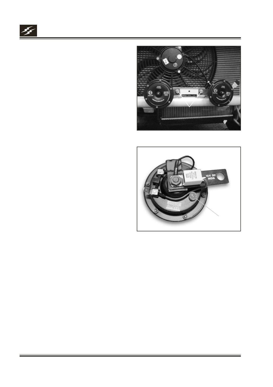
Horn Securing Bolts
Fig. 20
Setting
Screw
Fig. 21
11. Horn :
Remove
1.
Remove front number plate.
2.
Disconnect connection fromhorn.
3.
Removebolt securinghorn tomountingbracket. Fig.
20
4.
Remove horn.
Fitment
1.
Positionhorn tomountingbracket and tightennut.
2.
Connect blade terminals tohorn andbolt theground
/ earthingpoint.
3.
Fit front number plate.
Testing / Checking
a) Horn not working
l
Tightengroundproperly.
l
Check fuse & continuity.
l
Check relay & ensure it’s fitment in the base.
l
Fix connectors properly.
l
Check contacts of horn switch, adjust if required.
l
Check tuning of horn.
l
Replace the horn.
b) Horn Sound Deteriorated
l
Adjust setting screw till clean & sharp sound is
obtained. Fig. 21
Please refer Electrical Circuit of Audible Warning Devices