


 1411 / 1526

FUEL SYSTEM
6
Fig. 6
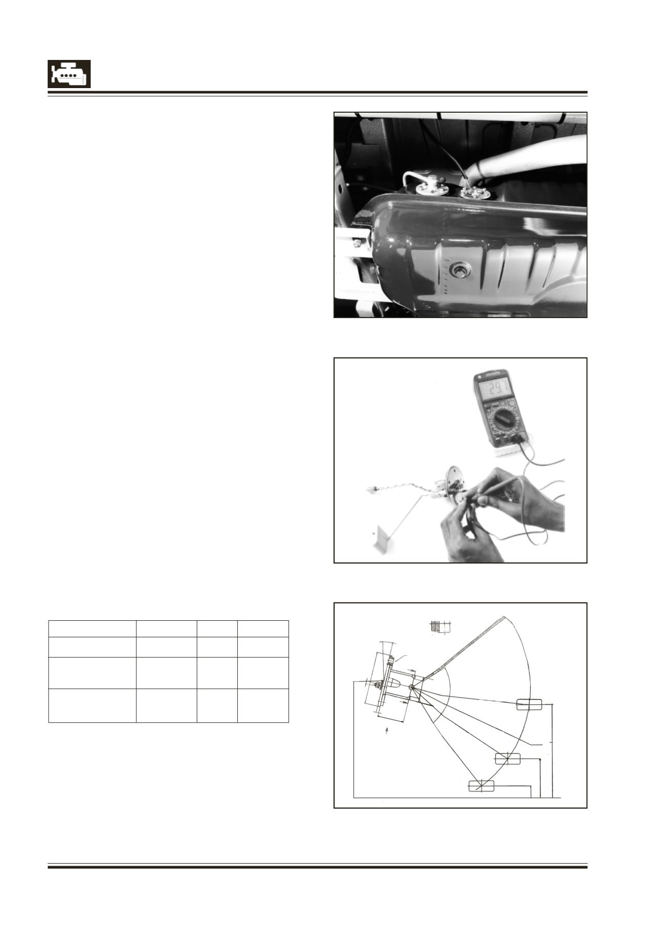
Fig. 8
Calibration Details :
Float Position Empty Half Full
Float Height
16.5
+2
133
+2
262
+2
Resistance
10
104 186
1N OHMS
Tolerance
+0
+8
+8
in OHMS
-4
Fig. 7
FUEL GAUGE TANK UNIT
Removal :
l
Remove electrical connections.
l
Remove 6 screws securing Float Unit from the fuel
tank.
l
Remove seal from the Float Unit.
Fitment :
Please follow reverse procedure
Assembly :
When installing fuel tank gauge, ensure that fuel tank
gauge unit assembled with O ring in place.
Testing / Checking :
Fig. 7 & 8
The sender is a float operated rotary potentiometer
which provides a variable resistance to ground for the
output from the gauge. When the sender float is at its
lowest point, indicating an empty fuel tank, the
resistance to earth is at its lowest. The resistance is
sensed by the gauge which positions the needle
accordingly.
Use ohm-meter to confirm that the resistance of the
fuel level sensor (Fuel Tank Unit) changes with the level
of float position.
15.00
DETAIL ‘A’
SCALE N
S
B
75.00
M4.00
X0.7
B
T
(90.00)
37.50
4.00
169.00
Fuel Tank Unit
R176.00+2
HALF
EMPTY
RESERVE